Fitting a GPS in a Raspberry Pi Compute Module 5 IO Case
Here is an example of how you can fit a GPS to the Raspberry Pi CM5 IO board in the official IO case, so that it can be used with SatPulse.
I chose a GPS in the form factor that I have found easiest to fit inside CM4/CM5 cases, which:
- is really small, almost thumbnail-sized; it is 17mmx23mm excluding the connectors and 17mmx40mm including the connectors;
- has a single hole that can be used to secure the board; it is small and light enough that a single hole is enough to securely support the board;
- has both U.FL (IPEX) and SMA connectors; the U.FL connector works best inside the case, but the SMA connector is useful for testing outside the case;
- has 5 Dupont pins for connecting power, serial port, and PPS; these are the same kind of pins that are used on the IO board, so is the easiest to work with;
- includes a tiny battery;
- has both power and PPS LEDs.
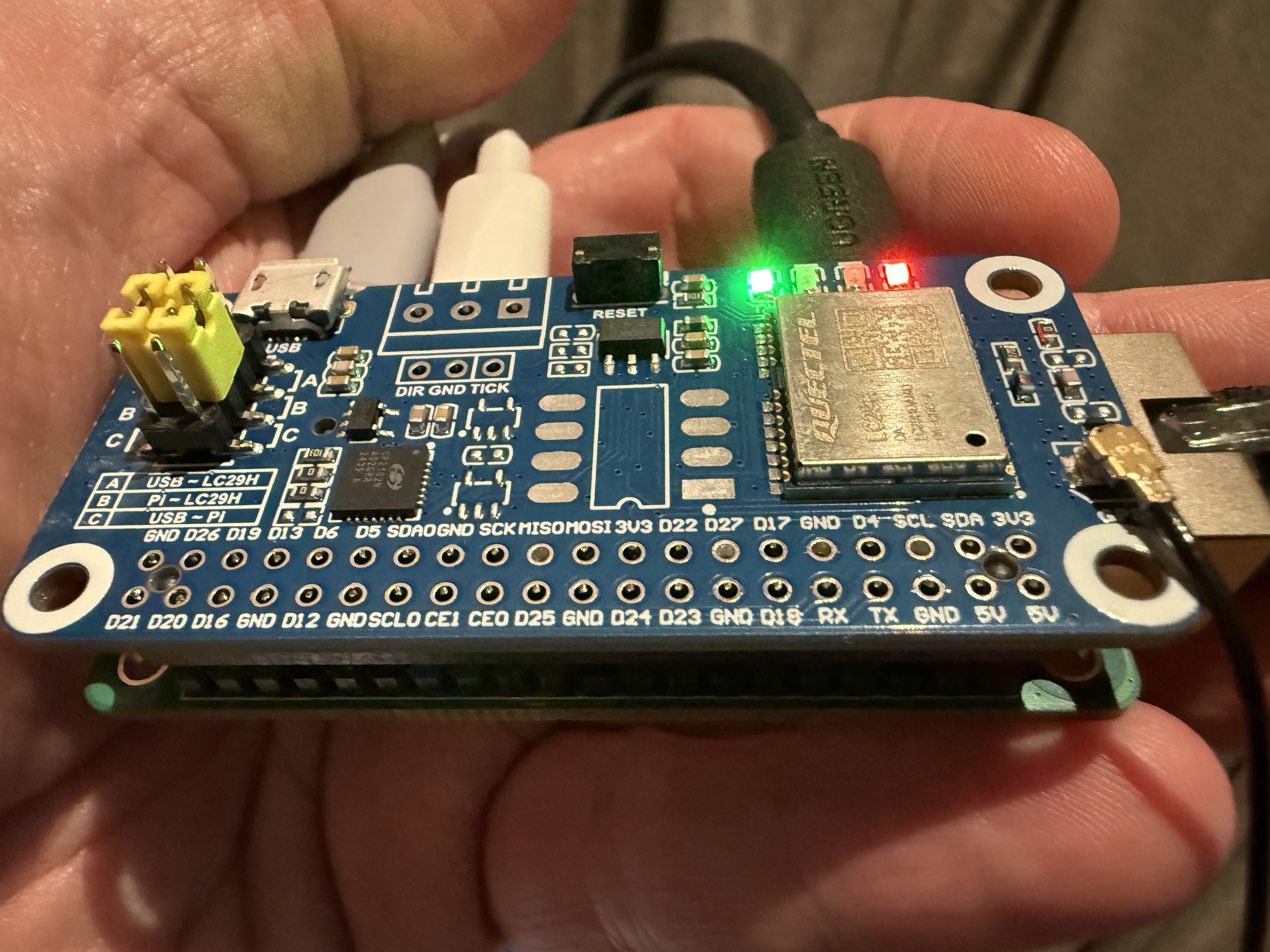
There are quite a number of GPSs on the market in this form factor. The board I am using here is the Star River SR1723U10. I got it from Star River’s official shop on AliExpress. (The shop is called Xing He Wei; Xing He means star river, which is a poetic name for the Milky Way in Chinese.) The SR1723 range has GPS boards in the same factor with a variety of different modules. This one uses the Star River SR1612U10 module, which uses the u-blox UBX-M10050-KB chip. So from a software perspective, it behaves like a u-blox 10th generation standard precision module. It costs about $7.
You will of course need an antenna; this module is single-band L1, so a basic GPS puck antenna with a cable ending in a SMA male connector is sufficient.
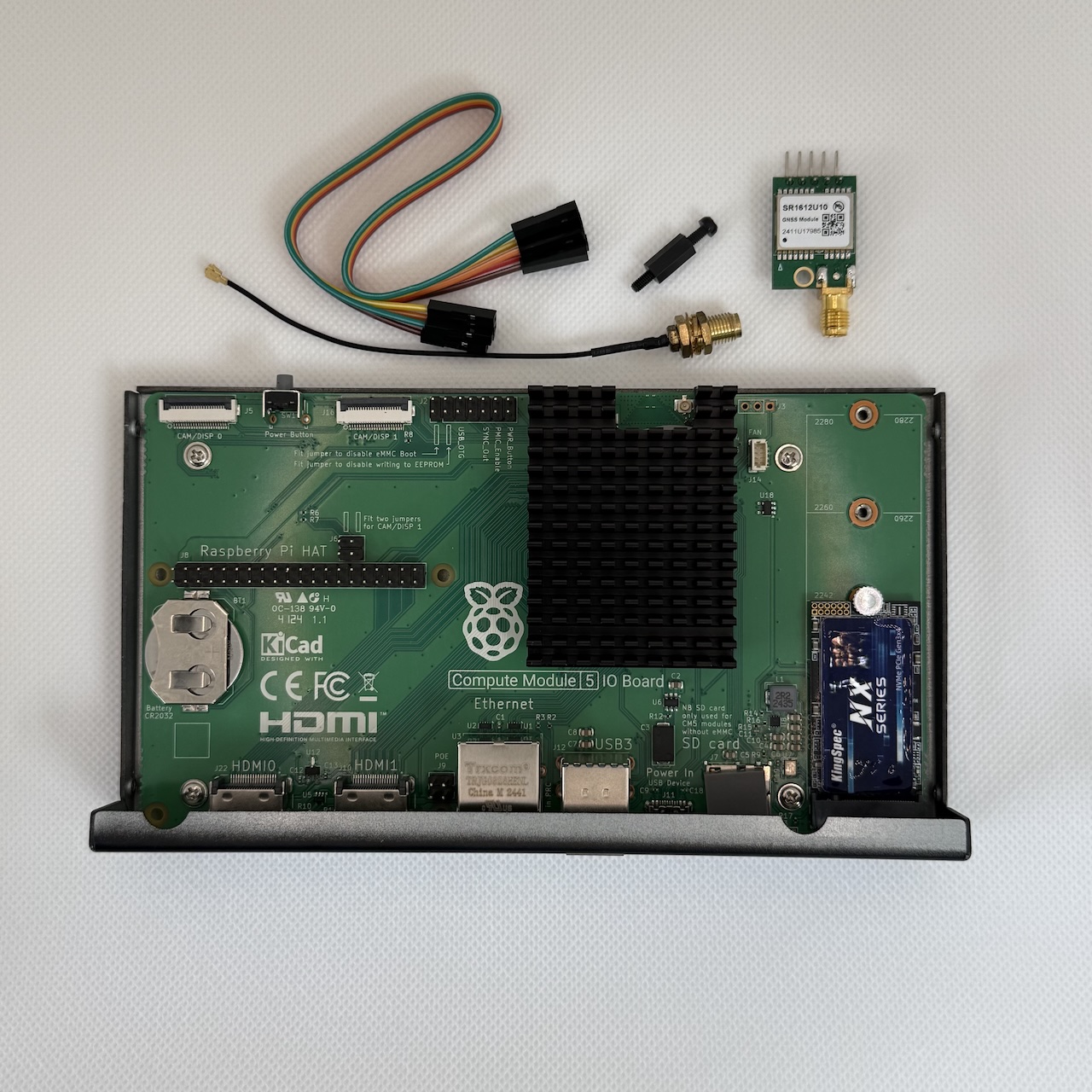
On the left we have the case assembled but without the GPS. The parts for this are:
- Raspberry Pi Compute Module 5
- Raspberry Pi Compute Module 5 IO board
- Raspberry Pi Compute Module 5 IO Case
- Raspberry Pi Cooler for Compute Module 5
- CR2032 coin cell battery for the RTC
You will also need a USB PD power supply, which I haven’t shown. Note that 5V3A is plenty for this configuration, so you can use any old USB PD power supply you have handy; there is no need to buy the special Raspberry Pi 27W supply which supports 5V5A.
To fit the GPS to the IO board, I used:
- a 15cm 5-pin Dupont female-female ribbon cable; this came with the GPS board; if you don’t have this, then you can just use 5 separate jumpers
- a 10cm U.FL to SMA female bulkhead pigtail (note that it is SMA female without a pin, rather than RP-SMA female with pin; RP-SMA is used for wifi antennas)
- a male-female 10mm M2.5 nylon standoff and screw
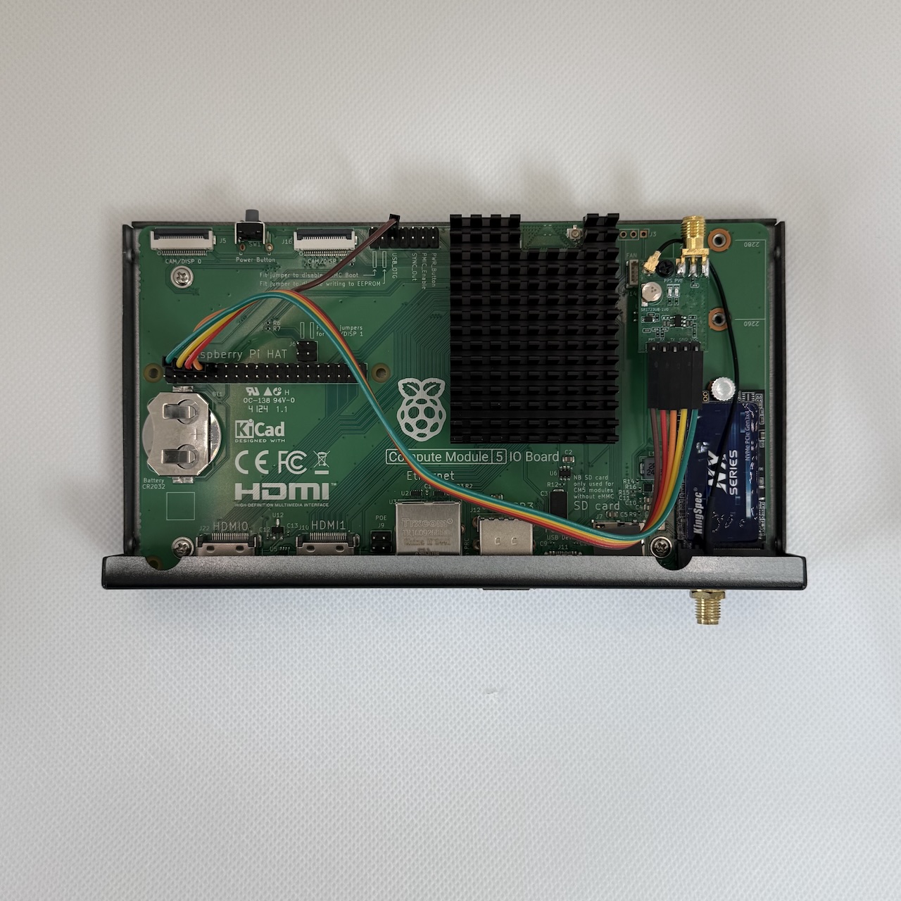
The assembled result is on the right. The assembly process involves
- removing the screw on the upper right that secures the board to the case, and replacing it by the standoff;
- using the hole in the case designed for a wifi antenna for the GPS antenna (rather surprisingly the wifi is still usable with the on-board wifi antenna)
| GPS Pin | Color | Pi pin # | Pi function |
|---|---|---|---|
| VCC | green | 4 | 5V |
| GND | yellow | 6 | GND |
| TX | orange | 10 | RXD0 |
| RX | red | 8 | TXD0 |
| PPS | brown | J6 - 6 | SYNC_OUT |
It is important to note here that silkscreen on the IO board labels pin 9 as the SYNC_OUT (as it was on the CM4 IO board), but this is incorrect: the SYNC_OUT pin is actually pin 6 (top row, third from the left, on the J2 14-pin jumper set). The VCC pin on the GPS accepts between 3.3V and 5V, so it could alternatively be connected to a 3.3V pin.
The setup guide explains how to install and configure the necessary software. The initial speed of the serial port is 38400.