Building a system using a Raspberry Pi Compute Model 4 or 5
Building the computer
The CM4 and CM5 are compute modules - they contain the processor, RAM, and usually storage, but need additional components to function as a complete computer. You’ll need the following parts to assemble a working computer:
- the compute module itself (a CM4 or CM5)
- a carrier board
- a case for the carrier board and compute module
- additional storage; this is needed only when using the CM4Lite or CM5Lite variants of the compute module, which do not have onboard eMMC storage; it can be either
- a microSD card, which works only with the CM4Lite or CM5Lite, or
- an M.2 NVMe SSD, which works only with the CM5, including the CM5Lite
- CR2032 coin cell battery for RTC
- a power supply
The CM4/CM5 come in many different configurations. Any configuration should work for our purposes
- RAM - 1Gb RAM should be enough, since we will not be installing a full desktop environment (I haven’t tested less than 4Gb)
- eMMC storage - all the carrier boards have a micro SD card slot, so eMMC storage can be used but is not essential
- wifi - we won’t be using wifi, because the antenna connector on the case is used for the GPS, but it doesn’t hurt to have it
There are many carrier boards available for the CM4/CM5, but we need one that gives access to the SYNC_OUT pin, and there are only a few of those. On the CM4, there are two sync pins, called SYNC_OUT and SYNC_IN, but actually SYNC_OUT does both input and output, and is the one that matters. On the CM5, there is only a SYNC_OUT pin.
The CM4 and CM5 have the same form factor and it is possible to use the CM5 with cases designed for the CM4 and vice-versa, but what will and will not work is not clearly documented, so I recommend not doing this.
The choice of case depends on the carrier board. It is important that the case has a hole designed for a wifi antenna. These holes are designed for an SMA bulkhead connector. We can repurpose this hole to be either a GNSS antenna input (for internal boards) or a PPS input (for external receivers.)
All the boards discussed below include a battery-powered Real Time Clock (RTC), which is useful. You will need to buy a CR2032 battery for it, unless you get the Edatec case, which comes with a battery.
CM4 carrier boards and cases
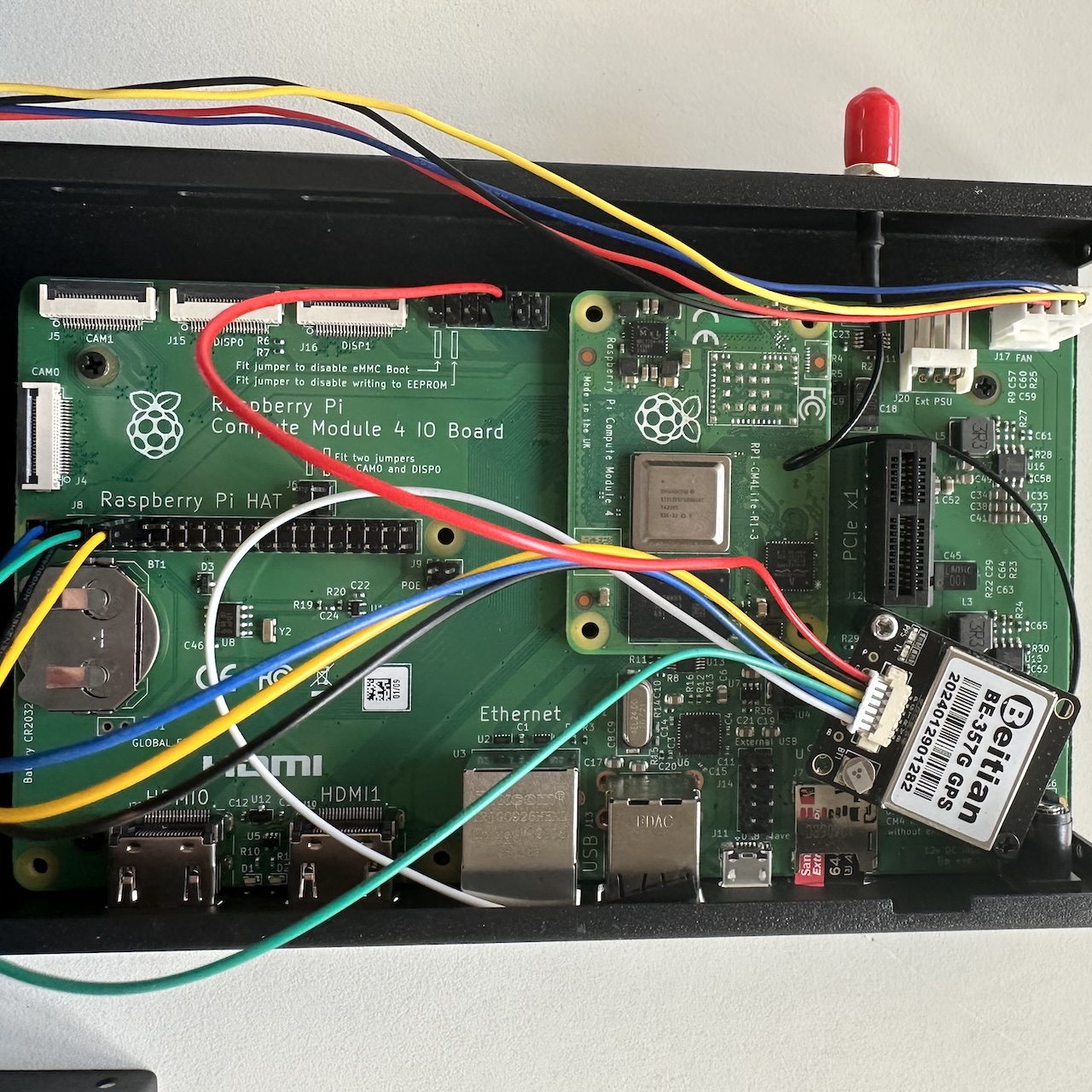
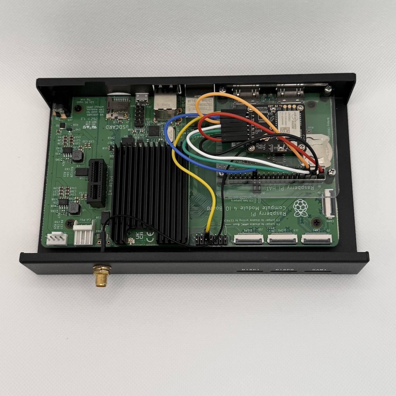
Raspberry Pi CM4 IO board
The obvious choice is the CM4 IO Board from the Raspberry Pi Foundation, which costs about $50. This is a good choice, if it’s available.
There are three suitable cases for this board:
- Waveshare case. There appear to be two versions of this. The newer version has a GPIO adapter that makes the 40-pin GPIO header available at the side; the older version does not. This adapter would get in the way of an internal GPS unit; if it’s not used, then there would be a hole in the side of the case.
- Edatec case
- Acrylic case
The Waveshare case has a significantly better fan than the Edatec case: it’s a 40mm fan and has PWM support, which matches the controller on the IO board. The Edatec case has a 25mm fan, which lacks PWM support.
The Waveshare case is also a few millimeters taller than the Edatec case, which makes it easier to fit an internal GPS unit.
The Edatec case comes with a Wifi antenna - but this isn’t very useful, since we will be using the antenna hole on the case for either the GPS antenna or a PPS signal.
The acrylic case is cheap, but there’s no way to fit a GPS inside it. I find it convenient for experimenting.
You will also need a 12V DC power supply with a 5.5x2.1mm barrel connector: 2A is plenty since we are not using the PCIe slot.
Waveshare boards
Waveshare make two boards that expose the sync pins. Each of these has its own case. You can buy the board without the case, but not vice-versa, so it makes sense to buy the board and case together.
I have the first of these. Compared to the official IO board, it
- does not provide a PCIe slot
- provides 4 USB 3.0 ports
- can be powered over PoE
- supports a wide-range of DC input voltages
The board fits snugly in the case with no spare space on any side, which makes it a little bit more difficult to fit an internal unit in. It’s a good choice if you are using an external GPS. The extra USB ports are more useful than the PCIe slot for this application.
CM5 carrier boards and cases
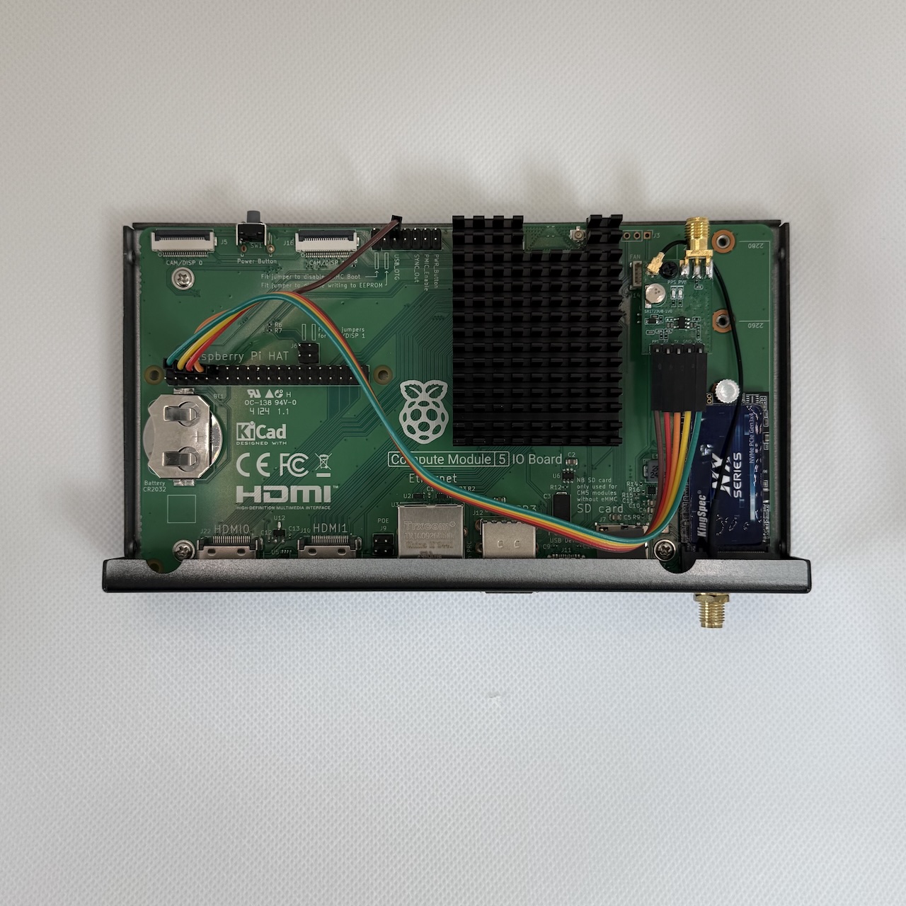
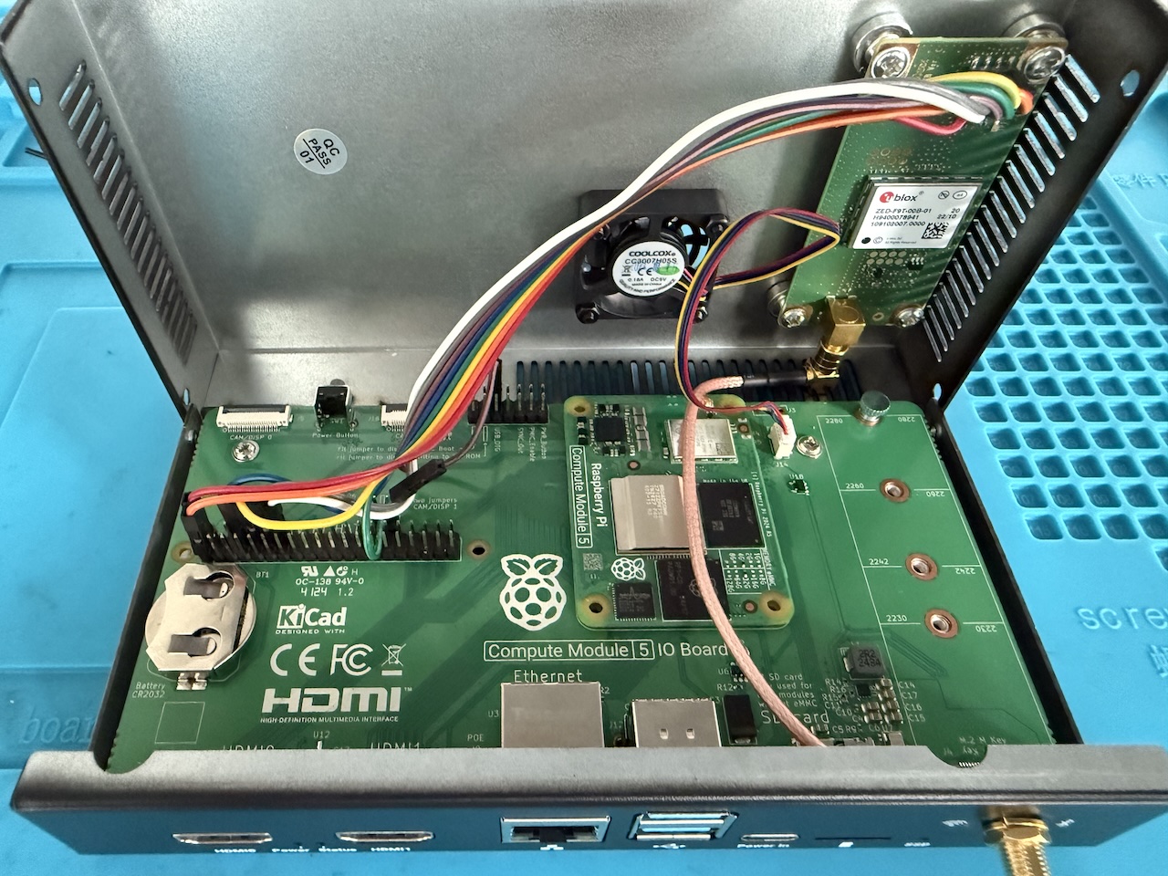
Official Raspberry Pi CM5 IO board
The obvious choice is the official CM5 IO Board from the Raspberry Pi Foundation, which costs about $25. It includes a slot for an M.2 NVMe SSD.
Note that there is an error in the silkscreen on the first version of these boards. The silkscreen labels pin 9 of the J2 jumpers as being the SYNC_OUT pin (as on the CM4 IO board), but the SYNC_OUT pin is actually pin 6 (above the pin labelled as USB_OTG).
There is also an official matching case, which I would recommend getting as well. The case comes with a fan, but you can also buy an official heatsink, which can be used instead of the fan and gives a quieter system.
Waveshare CM5 PoE board
Waveshare make a carrier board, which is also available as a mini-computer kit that includes a case and a power supply. This supports PoE.
It includes a 40-pin GPIO adapter, which makes the Raspberry Pi 40-pin header available outside the case. This makes it easy to connect it to a GPS board outside the case. If you want to put the GPS board in the case, then you can remove this adapter, but this leaves a hole in the case.
Power supply
The above carrier boards all require a USB PD power supply.
They can make use of a 5V5A power profile and Raspberry Pi have an official 27W USB C power supply that can provide this. Only a few 3rd party power supplies support this. One example is from Radxa; this has a separate cable, folding prongs, and separate side-on plug adapters for European and UK sockets. Note that 5V5A as a PPS does not work: a fixed PDO is necessary.
However, in practice, I have found a 5V3A power supply to be plenty when using a CM5 as a time server.
Connecting an external receiver
An external receiver needs two connections: a PPS connection and a serial connection.
PPS connection
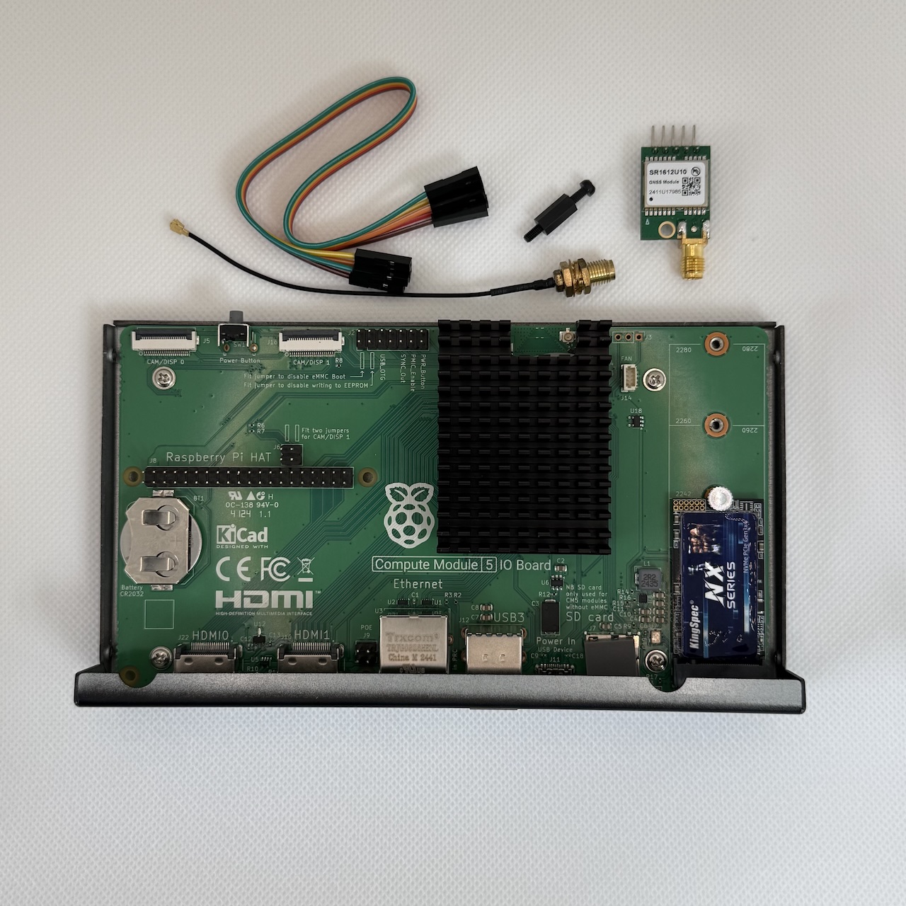
For the PPS connection, we repurpose the wifi antenna hole in the case as a PPS input connector. You’ll need a cable with a female bulkhead SMA connector on one end that mounts in this hole.
The other end of the cable needs to connect to the SYNC_OUT pin and a GND pin. There are two ways to do this:
- Use a cable that has the SMA connector on one end and two female Dupont pins on the other end. You can get suitable cables on eBay and AliExpress.
- Use a purpose-built board from Timebeat that fits on top of the J2 jumpers and provides U.FL connectors. You can then use a readily available U.FL to SMA pigtail.
The PPS connection goes via an SMA connector that is brought out from the SYNC_OUT pin through the hole intended for the wifi antenna to a female bulkhead SMA connector.
Note that the female SMA connector here needs to be SMA not RP-SMA. RP-SMA connectors are used for wifi. A female SMA connector has a hole in the center, whereas an RP-SMA connector has a pin in the center. This means that you cannot use the U.FL to RP-SMA pigtail that comes with the official antenna kit.
The external receiver will typically also have a female SMA PPS output. You can connect this to the female SMA PPS input on the computer using a SMA male - SMA male cable.
Serial connection
The serial connection normally goes via a USB A port on the IO board.
If the external receiver has a USB port (typically micro USB or USB C), then you use an appropriate USB A to USB cable. If the receiver is a USB dongle with a male USB A connector, you can plug it directly into the IO board or use a USB A male to female extension cable.
If the external receiver has an RS232 DB9 port, then you use a USB to RS232 DB9 male adapter cable.
Using internal board
Connecting an antenna
For the antenna connection, we repurpose the wifi antenna hole in the case as a GNSS antenna input. You’ll need a pigtail with a female bulkhead SMA connector on one end that mounts in this hole.
The other end of the pigtail needs to fit the antenna connector on the board. A length of 15cm is about right. The most common kind of board antenna connector is U.FL, also called IPEX. The board has a female jack (receptacle), so the pigtail needs a U.FL male plug. Some other boards have a MMCX female jack, so the pigtail needs a MMCX male plug. The telecom form factor board has an SMB male jack, so the pigtail needs an SMB female plug. (SMB reverses the usual male/female convention for what goes on the board vs what goes on the jack.)
Connecting to IO board pins
The board needs to be connected to pins on the IO board to receive power and to make a serial connection to one of the Raspberry Pi UARTs.
Cabling
This is easiest if the GPS board has 2.54mm Dupont pins; in this case, you just need female-female Dupont jumpers.
Otherwise you need a cable with something that fits the board on one end and Dupont female connectors on the other end. 15cm is long enough.
For telecom form factor boards, you can buy a 20cm cable consisting of a strip of 40 wires, with one end having 2.54mm Dupont 1-pin female connectors and the other end having 2.0mm 2-pin female Dupont connectors AliExpress, AdaFruit, eBay
Wiring
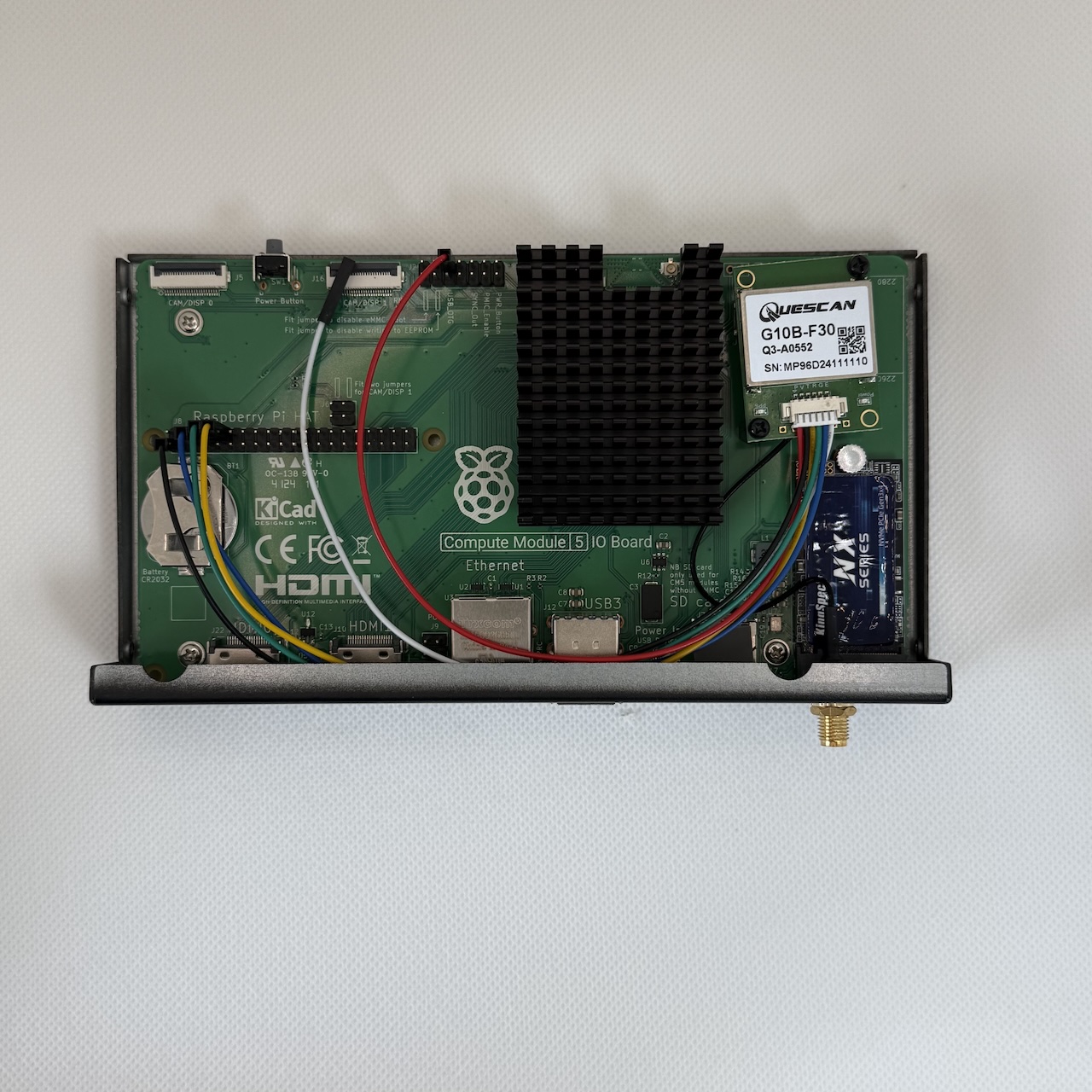
The Dupont female connectors need to be plugged into the IO board pins according to the following table. HAT refers to the main 40-pin header. J2 refers to the 14-pin header in the top center. In both cases, pin 1 is the bottom left: the lower row of pins are odd-numbered; and the upper-row are even-numbered.
| IO board | Jumpers | CM4 pin# | CM5 pin# | GPS board |
|---|---|---|---|---|
| 3V3 | HAT | 1 | 1 | VCC (if 3.3V) |
| 5V | HAT | 4 | 4 | VCC (if 5V) |
| GND | HAT | 6 | 6 | GND |
| TXD | HAT | 8 | 8 | RX |
| RXD | HAT | 10 | 10 | TX |
| SYNC_OUT | J2 | 9 | 6 | PPS |
Note that the silkscreen on official CM5 IO board does not correctly label the SYNC_OUT pin: SYNC_OUT is pin 6 not pin 9 on the J2 jumpers.
GPS boards typically accept a voltage range of 3.3V-5V. But be sure to check the board’s spec before connecting it to a 5V pin on the IO board. If the board accepts 3.3V-5V, I recommend first connecting it to the 3.3V pin on the IO board. Once everything is working, you can connect it instead to the 5V pin. If you connect 5V to the wrong pin on the GPS board, you can fry your GPS board (I have done this).
The telecom form factor boards have separate pins for the board power and antenna power. The pin for board power should be connected to a 3.3V pin on the IO board. The pin for antenna power should be connected to a 5V pin on the IO board.
Mounting
A bit of ingenuity and improvisation is needed to mount the GPS board in the case. The approaches that can be used depend on the size of the GPS board and the number and size of its mounting holes. The first two approaches are cheap and easy, but don’t work if the board has holes that are M2 or smaller. The third approach, with an adapter plate, takes a bit more effort, but can work with all sizes of mounting holes.
Using mounting holes in IO board
The IO board case uses M2.5 threaded standoffs. The IO board is attached to these using M2.5 screws.
If the holes in the GPS board fit M2.5 screws, then things become easier. You can remove one of screws and replace it by the male end of a 10mm female/male standoff. The GPS board can then be attached to the female end of the standoff with a screw.
This is particularly simple if the board is small enough that it has only a single hole. The threaded standoff at the top right of the IO board usually works well.
Otherwise, you can attach a nylon 10mm female/female standoff to one or more of the other mounting holes of the GPS board; the female standoffs rest on the IO board and are not screwed in, but they ensure that the board is properly supported. The male/female standoff that is screwed in ensures the board does not move around too much. Using nylon standoffs ensures no electrical shorts even if it does move a little.
Magnets
The idea here is to attach magnetic stands to the holes in the GPS board, and then use these to attach the board magnetically to the inside top of the metal case.
There are magnetic stands available with posts threaded to accept M3 screws. So if the mounting holes in the GPS board accept M3 screws, you can screw the board directly to these stands.
If the holes in the board are too small for M3 screws, then you can instead use magnets that have countersunk holes designed to accept screws. For example, if the board takes M2.5 screws: an M2.5 screw goes through the GPS board into one end of an M2.5 female-female standoff, and an M2.5 countersunk screw goes through the magnet into the other end of the standoff. The countersunk screw doesn’t protrude from the magnet, allowing the magnet to sit flat against the case.
Acrylic adapter plate

The concept here is to get laser-cut acrylic plate custom made. The IO board has holes in it that fit standard Pi HAT dimensions. The adapter plate has a set of 4 outer M2.5 holes that matches with these IO board holes, plus a cutout to provide access to the 40-pin header. It then has a set of 4 inner holes to fit the GNSS board. The plate is attached to the IO board with 10mm standoffs. The GNSS board is attached to the adapter plate using short standoffs or washers, just tall enough so the underside of the GNSS board does not touch the adapter plate.
It is surprisingly inexpensive to get a custom laser-cut acrylic plate made (at least where I live). I got the above plate made for about USD6. The laser cutting service were able to work with an SVG produced using Inkscape; you can modify the one above to fit your board. You need the precise mounting hole pitch (center to center distance) of the mounting holes. The hole size needs to be 0.2mm bigger than the screw size (e.g. 2.7mm for M2.5). I specified a thickness of 2mm.
Using a sandwich board
The Timebeat sandwich board has a unique form factor that fits between the CM4/CM5 and the carrier board.
This allows it to connect the CM4/5 pin for SYNC_OUT to GNSS PPS out, and the GNSS TX/RX into the CM4/5 UART TX/RX pins. This gives the simplest possible installation, with no cabling required between the sandwich board and the IO board pins. It also opens up the possibility of using carrier boards that do not expose the SYNC_OUT pin.
The sandwich board still has a U.FL connector for antenna input, that allows an antenna to be connected as with other internal boards.