Building a system using an Intel Ethernet controller
There are several affordable Intel Ethernet controllers that support PPS input and have Linux drivers: i210, i225 and i226. The i226 has replaced the i225. These controllers are available in a number of different cards.
The i210 supports 1Gbps, whereas the i225/i226 support 2.5Gbps. The i225/i226 can support PTM when used in a suitable system.
In Intel controllers, the PPS input capability is provided by Software Defined Pins (SDPs). The SDPs can be used for output as well as input. At the controller level, SDPs are I/O pins on the controller chip, but these are only useable if the card exposes them as a pin header.
The i210 uses the Linux igb driver. The i225/i226 use the igc driver. These both have solid, mature PTP support, which includes support for the SDPs. The i210 has an openly available data sheet, which provides complete programming information; the i225/i226 do not.
PC system
To build a PC system, we use a PCIe card with an Intel Ethernet controller. The key point is that the card needs to expose the SDPs provided by the controller.
I210-T1
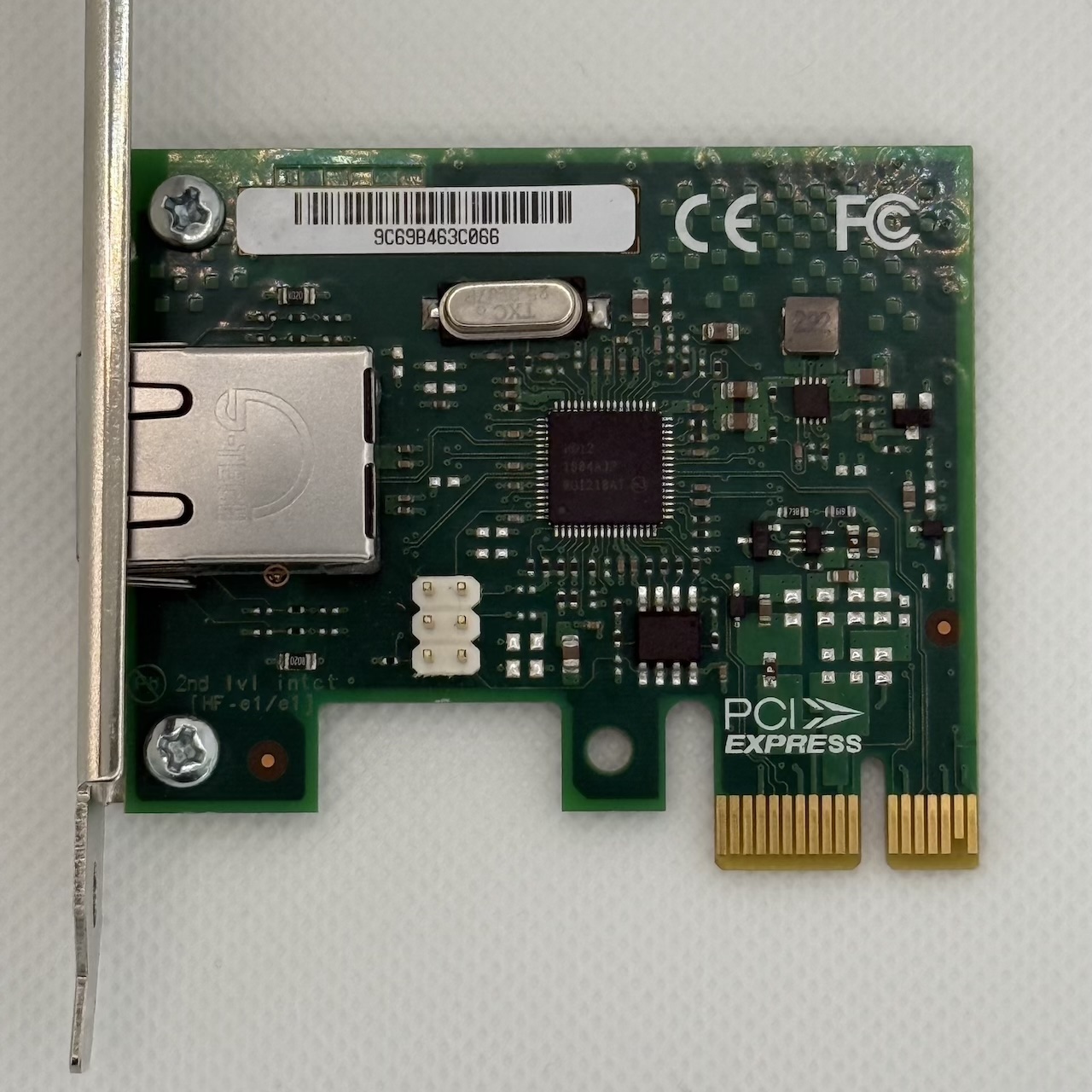
The most commonly used network card with a PPS input is the Intel I210-T1. Although it’s a 10-year old product, it remains an excellent choice.
As well as the original Intel cards, there are OEM versions that work fine and are cheaper, but you need to choose ones that have the same layout as the Intel original and include the 6-pin SDP header. The only visual differences between the OEM version and the Intel original are
- the OEM version does not have the Intel logo, and
- with the OEM version, the board attaches to the bracket using two screws, whereas the Intel original uses a screw at the bottom and a hook at the top.
The i210-T1 card has a 3x2 male pin header, which expose the Software Defined Pins (SDP) of the i210 controller. The pin header has a pitch of 2.54mm (0.1”) and is compatible with Dupont female connectors. Orienting the card with the RJ45 connector on the left, the top right pin is SDP0, the middle right pin is SDP1, and the middle left pin is GND.
TODO: Get clear about the other pins. Top left is probably GND. Bottom right might be SDP2. Bottom left is probably not GND.
The i210-T1 comes with both full and half-height brackets.
I226-T1
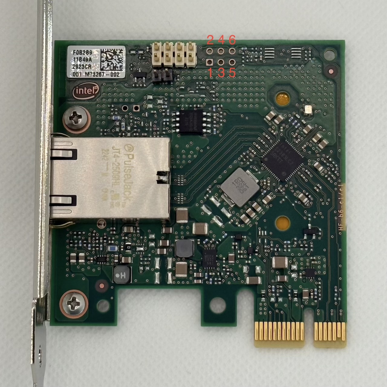
The I226-T1 is Intel’s card using the i226.
Unlike the I210-T1, the I226-T1 does not come with a pin header for the SDPs. But it does have a header pad (through holes) onto which a pin header can easily be soldered.
The functions of the pins (as numbered in the above photo) are as follows:
| Pin | Function |
|---|---|
| 1 | SDP0 |
| 2 | GND |
| 3 | SDP1 |
| 4 | GND |
| 5 | SDP2 |
| 6 | GND |
Timebeat sell a modified version of the i226-T1 with the headers soldered on and a breakout board that provides U.FL connectors for the three SDP pins and DIP switches. The DIP switch enables 50 Ω termination and should be on when the corresponding pin is being used for output.
The i226-T1 comes with both full and half-height brackets.
TimeAppliances TimeNIC
TimeAppliances make the TimeNIC, which is a PCIe card with i226 controller. It has a full-height bracket that provides SMA connectors for PPS input and PPS output, which are connected to SDP0 and SDP1.
It also has a TCXO, which should improve the stability of the PHC.
Connecting a GNSS receiver
This section deals with connecting an external GNSS receiver with its own enclosure. It also applies to GNSSDOs.
PPS connection
PPS signals on external GPS receivers are usually coaxial connectors, typically female SMA. The ethernet controllers expect 3.3V TTL-level signal not a 5V signal. So it is crucial to connect to an external receiver that also uses 3.3V. Note that the connectors conventionally used for wifi antennas are RP-SMA, which is not compatible with SMA: with RP-SMA connectors, the connector with the screw thread on the outside has a pin; with SMA, it has a hole.
The TimeNIC comes with an external female SMA connector, so it is trivial to connect to the SMA connector on the external receiver: just use a male SMA-male SMA cable.
With the other two cards, we need to first create an external female SMA connector. This can be done by using a PCI bracket with a hole for an SMA connector: these are designed for use with antennas of wifi cards. You can buy them on AliExpress; they are available in full height, or half height, and with two or three holes. This requires a spare slot in the case close to the slot used by the PCIe card.
Then you use a short pigtail to connect the hole in the PCI bracket to the PCIe card. The pigtail will have a SMA female bulkhead connector on the PCI bracket end. The card end of the pigtail depends on whether you are connecting to the Dupont pins on the PCIe card or to the breakout board.
- If connecting to the Dupont pins, you need a cable with Dupont female connectors. The complete cable is called an SMA female bulkhead to Dupont female RG316 test cable. The test cables I have bought are wired so that black is the shield and red is the inner conductor. This means the black wire needs to be plugged into a GND pin on the SDP headers, and the red wire needs to be plugged into SDP0 or SDP1.
- If connecting to the U.FL connectors on the breakout board, you need a normal SMA female bulkhead to U.FL pigtail.
The method described here directly connects the pins on the i210/i226 to the PPS signal, without providing any electrical isolation. Directly connecting a 3.3V PPS signal works for me, but I’m not an electrical engineer, and I do not have a good understanding of the risks (if any) involved here. So proceed at your own risk. Here is a description of connecting via a RS232-TTL converter. (My understanding is that using a RS232-TTL converter like this allows you to safely connect a 5V PPS signal.)
TODO: Need to understand and make recommendations regarding grounding. Using the PCI bracket establishes a ground connection to the case; not sure if that helps. There are a number of other things that we could do that might help. The GPS could be powered via a USB port on the PC. The PC could be one that is powered via a separate AC/DC converter, which would mean it has a floating ground.
Serial connection
If the external receiver has a USB port, it should be connected to a USB port of the PC. If the external receiver has an RS232 female DB-9 port, it can be connected to a RS232 male DB-9 port on the PC if it has one, and otherwise to a USB port of a PC using a RS232-USB adapter cable.
Connecting M.2 GNSS card
There are M.2 cards with GNSS modules that fit an M.2 key E slot intended for a Wifi card. They appear as USB devices and have U.FL connectors for antenna input and PPS output.
An I226-T1 card with the Timebeat breakout board can be combined with such an M.2 card to create a neat system that does not need an external receiver.
For this, I recommend getting
- a PCI bracket with 3 holes (designed for antennas for wifi cards)
- 3 SMA female bulkhead to U.FL pigtails
- a U.FL to U.FL pigtail
These are connected as follows:
- the U.FL to U.FL pigtail connects the PPS output of the M.2 card to one of the U.FL connectors on the breakout board
- one of the SMA to U.FL pigtails goes from one of the holes on the PCI bracket to the antenna input on the M.2 card
- the remaining two SMA to U.FL pigtails go from the remaining two holes on the PCI bracket to the remaining two U.FL connectors on the breakout board.
Connecting a GNSS board
It is also possible to connect a GNSS board to a PC. In this case, the board will live outside the PC, which means it is not very elegant or robust, but it does work.
For this, you should choose a GNSS board with
- M3 mounting holes
- Dupont pin connectors
- SMA antenna connector (not essential but convenient)
Suitable boards are available very cheaply, so this is a cheaper option than using a GNSS receiver.
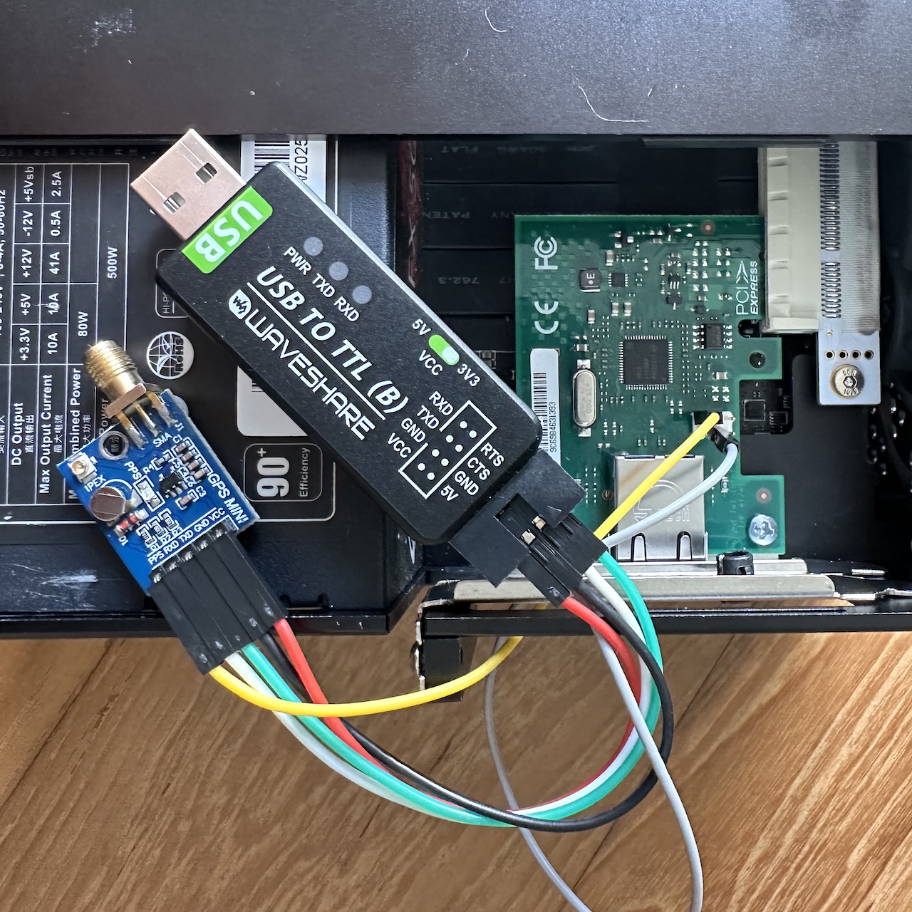
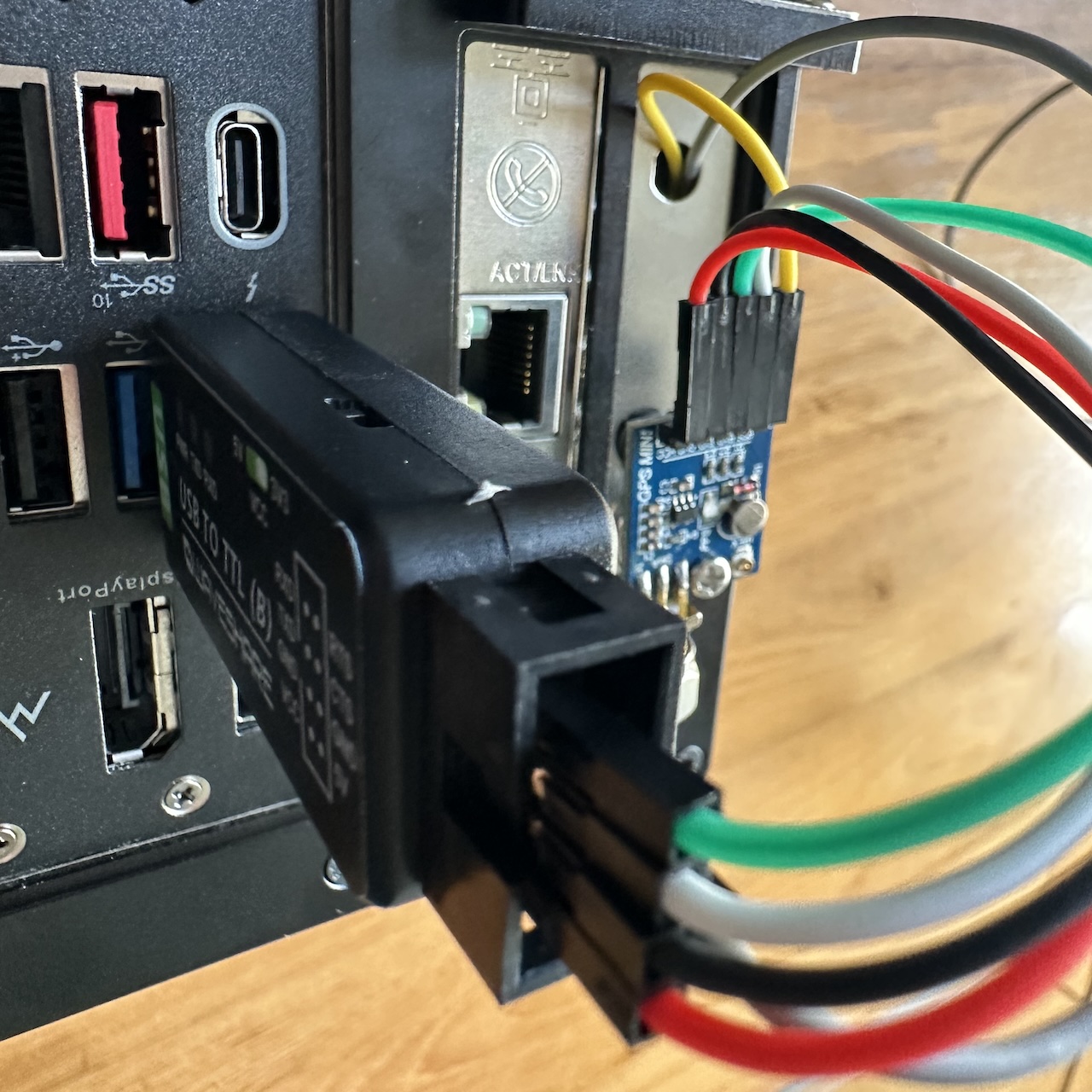
This is combined with a USB-to-TTL converter that also has Dupont pins.
These need to be wired up as follows:
| Color | GNSS pin | USB to TTL pin | NIC pin |
|---|---|---|---|
| black | GND | GND | - |
| red | VCC | VCC | - |
| green | TXD | RXD | - |
| white | RXD | TXD | - |
| yellow | PPS | - | SDP0 |
| grey | - | GND | GND |
Note that two GND connections are needed to the USB-to-TTL converter. Most converters only have one pin, which would require improvisation. But Waveshare make a converter with two GND pins; there are two versions, one with the FT232RL and one with the CH343G. You can get these from AliExpress for about $10 or directly from Waveshare (but shipping is more expensive). The Waveshare converter comes with a cable with Dupont connectors, but it is likely to be too short. I’m using some separate Dupont female-female jumpers to wire things up.
To mount the board securely use M3 female magnetic screws to attach the module to the backplate or to the case (if it’s steel rather than aluminium). The GPS antenna is attached directly to the SMA connector on the module. This setup is rather vulnerable to the antenna cable being yanked: I recommend clamping the antenna cable to the table.
Building a small form factor PC
Any old spare PC will work fine provided it has a spare PCIe slot.
In the following sections, I describe two ways of building something much smaller than a normal PC, using an HP thin client or a Lenovo Tiny desktop.
HP Thin Client
The HP T740 thin client is available on eBay for about $200. It is unusual in that it has single PCIe slot that accepts standard low-profile cards on a standard low-profile bracket, while being only 2.2L in size. It also has an M.2 wifi slot.
There’s a review on ServeTheHome.
It comes with an eMMC card, but I wasn’t able to boot from this after installing Linux. I installed an inexpensive M.2 NVMe card in place of the eMMC card and that worked fine.
I had a problem with the BIOS not detecting the CPU fan on boot. This was fixed by upgrading the BIOS. Upgrading the BIOS required downloading and running a program on Windows 10 (Windows 11 didn’t work) to create a disk, which the BIOS could use to update itself.
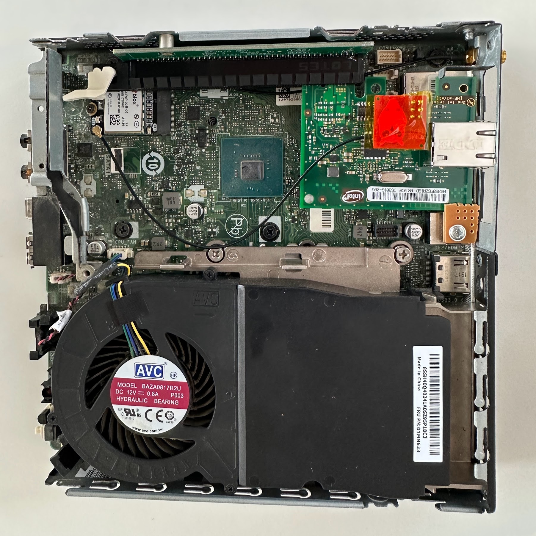
This shows a T740 with a cable attached to the i210, before plugging the i210 into the PCIe slot.
Lenovo Tiny desktop
Some Lenovo Tiny desktops have a slot into which you can put a riser that accepts low-profile PCIe cards, but without their bracket.
I recommend buying a second-hand M720q. These are widely available. Try to get one without a wifi card, because we will use the wifi antenna hole to connect with the GPS or i210 card. It should also work with an M920q or M920x.
There’s a review of the M720q on ServeTheHome.
The M720q has space for a 2.5” disk (usually an SSD), but you cannot use this at the same time as a riser. So you will need to remove the 2.5” disk and install an M.2 drive (there is space for one under the bottom cover).
You will also need to get a kit which has the riser, a cover plate with an opening (sometimes sold as a baffle or a bezel) and some screws. The Lenovo part number is 01AJ940 (this is just the riser, I believe). These are available from AliExpress or eBay (search for 01AJ940).
The cover plate is designed for a 4-port i350 card. This means that the opening is bigger than necessary for a single RJ45 card. More importantly, the cover plate has a clip that is designed to retain a low-profile card that occupies the full-height of the low-profile bracket. The i210 card is shorter and so the clip does not work to keep it in place. Improvisation is therefore necessary to keep the clip in place.
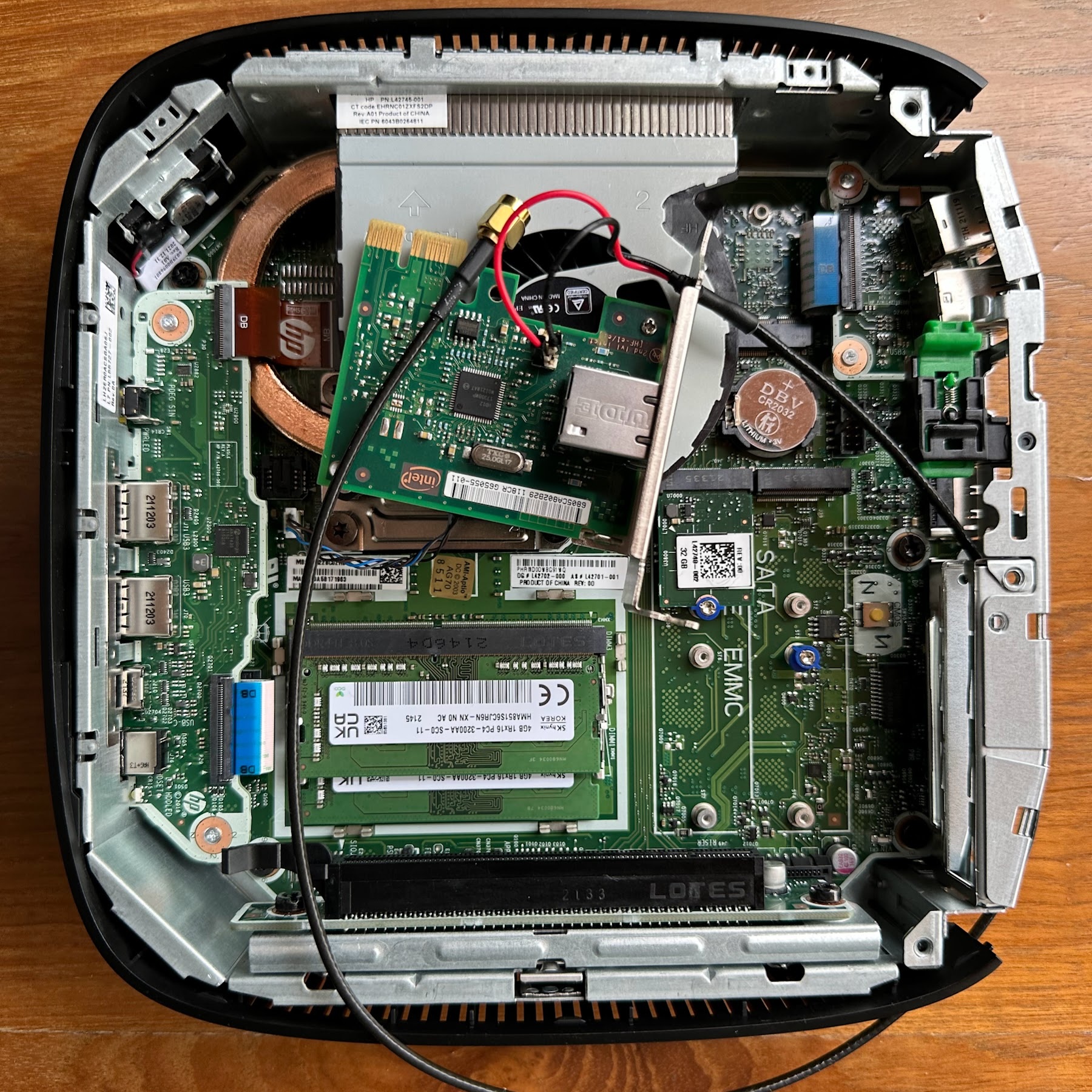
The rear of the PC has a small hole that can accept an SMA female bulkhead connector. In models without wifi cards, the hole is covered by a disc with a little slit, which can be pushed out with a screwdriver. We can then fit a pigtail with an SMA female bulkhead into this hole.
This shows a build using an i210 and the ArduSimple M.2 card. There is U.FL to SMA female bulkhead cable going from the rear of the computer to the antenna input on the M.2 card. The i210 is fitted with the breakout board from Timebeat. I’ve put a piece of Kapton tape on top, since the breakout board can come into contact with the case (electrical tape would probably have been better). There is then a U.FL connector going from this breakout board to the PPS connector on the M.2 card. I’ve improvised a way to keep the i210 in place using a couple of pieces cut off the corner of a stripboard.
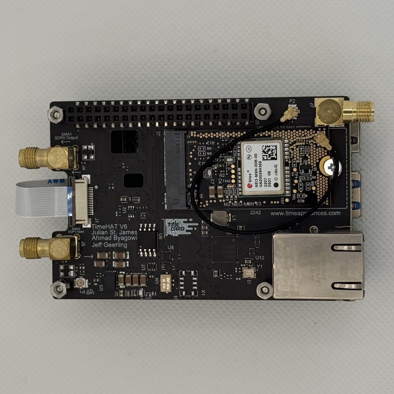
TimeAppliances TimeHAT
TimeAppliances make the TimeHAT, which is a hat for the Raspberry Pi 5 that has an i226 controller and an M.2 card slot for a GNSS card. Like the TimeNIC, it also has a TCXO, which should improve the PHC stability. The PPS output of the GNSS module on the M.2 card has an internal connection to SDP2 on the controller. It also provides SMA connectors that expose SDP0 and SDP1 for PPS output and input respectively.