Configuring UARTs on Raspberry Pi CM4/CM5
If you have a Raspberry Pi CM4/CM5 and you are connecting the TX/RX pins on the GPS board to
the 40-pin HAT connector on the carrier board, then you need to configure the UARTs.
A UART (Universal Asynchronous Receiver-Transmitter) is a hardware device that transforms
between digital data and a serial signal.
The CM4/CM5 include several UART devices, which are numbered starting from 0.
UARTn will appear as the serial device /dev/ttyAMAn.
Raspberry Pi’s official documentation has a section on this.
These instructions are for Raspberry Pi OS. There is a separate section for Fedora at the end.
Using UART0
The normal configuration is to use UART0 for the connection to the GPS. With this configuration, the GPS TX/RX pins are connected to the 40-pin HAT as follows.
| HAT Pin Name | HAT Pin # | GPS Board Pin |
|---|---|---|
| TXD0 | 8 | RX |
| RXD0 | 10 | TX |
Note that the connection is crossed: GPS RX connects to HAT TXD0, and GPS TX connects to HAT RXD0. This uses the TXD0/RXD0 pins, which are the pins for UART0.
This requires that UART0 is not used for a serial console but is enabled.
To configure this, run raspi-config and under Interface/Serial port, select enable serial port.
Then answer:
- No to login shell accessible over serial (this removes
console=serial0,115200from/boot/firmware/cmdline.txt) - Yes to enable serial port hardware (this adds
dtparam=uart0=onorenable_uart=1to/boot/firmware/config.txt, depending on whether it’s a CM5 or CM4)
Also, for the CM4, but not the CM5, add the following at the end of /boot/firmware/config.txt:
# Make /dev/ttyAMA0 be connected to GPIO header pins 8 and 10
# This always disables Bluetooth
dtoverlay=disable-bt
and disable the system service that initialises the Bluetooth modem:
sudo systemctl disable hciuart
Using other UARTs
If you want to use a UART other than UART0, that is also possible.
For example, if you want to use UART3 on the CM4, then add
dtoverlay=uart3
to the end of /boot/firmware/config.txt. On the CM5, use instead:
dtoverlay=uart3-pi5
Then reboot. After rebooting you can find which pins UART3 is on by using
pinctrl -p | grep '= [TR]XD3'
The pins will be different on the CM4 and CM5. On a CM5, it will print
21: a2    pu | hi // GPIO9 = RXD3
24: a2    pn | hi // GPIO8 = TXD3
which means that TX for the UART3 is on pin 24 and RX is on pin 21.
Fedora
Fedora has a number of differences relevant to UART configuration:
- Fedora uses U-boot and U-boot by default enables the serial console on UART0. If the GPS is connected to UART0, U-boot tries to interpret output from the GPS as keyboard input to U-boot, which causes the boot process to halt. (Although in theory we could make U-Boot not do this, keyboard input to U-Boot appears not to be working at the moment, so this would require a custom version of U-Boot.)
- Fedora uses
/boot/efi/config.txtrather than/boot/firmware/config.txt - Fedora doesn’t have the
pinctrlutility. - Fedora doesn’t yet support the CM5
Fedora has some documentation on Raspberri Pi HATs that is also applicable to the CM4 with an IO board (even without additional HATs).
You need to use UART3 or UART4 instead of UART0 for connecting the GPS.
You can enable UART3 by adding this to the end of /boot/efi/config.txt.
# UART configuration
# Make UART3 TXD, RXD available on pins 7, 29 (GPIOs 4, 5) respectively
# Device will be /dev/ttyAMA3
dtoverlay=uart3
You can use UART4 instead with the following:
# Make UART4 TXD, RXD available on pins 24, 21 (GPIOs 8, 9) respectively
# Device will be /dev/ttyAMA4
dtoverlay=uart4
This table summarizes the UARTs, GPIOs and pins for UART0, UART3 and UART4 on CM4:
| UART# | TX GPIO | RX GPIO | TX pin | RX pin |
|---|---|---|---|---|
| 0 | 14 | 15 | 8 | 10 |
| 3 | 4 | 5 | 7 | 29 |
| 4 | 8 | 9 | 24 | 21 |
This means that the GPS would be wired as follows:
| GPS pin name | HAT function | UART0 pin | UART3 pin | UART4 pin |
|---|---|---|---|---|
| RX | TXD | 8 | 7 | 24 |
| TX | RXD | 10 | 29 | 21 |
Here’s an example assuming we are using the uart3 overlay.
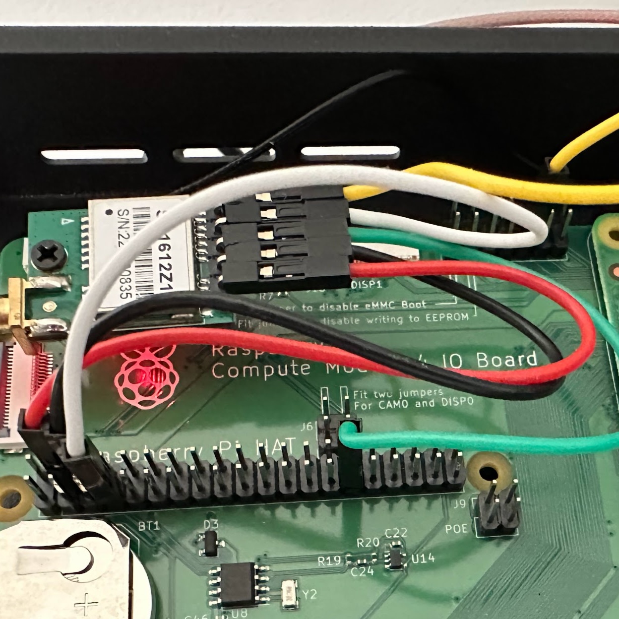
The wiring is as follows
| Color | GPS pin | Jumpers | Pin # | Pin function |
|---|---|---|---|---|
| yellow | PPS | J2 | 9 | SYNC_OUT |
| white | RX | HAT | 7 | GPIO 4, TXD3 |
| green | TX | HAT | 29 | GPIO 5, RXD3 |
| black | GND | HAT | 6 | Ground |
| red | VCC | HAT | 4 | 5V power |