GNSS boards and cards for timing
This page discusses GNSS boards and cards that are suitable for timing applications and are designed to be mounted inside a computer case.
The following points should be considered for all boards:
- What GNSS module does it use? The choice of module is discussed in the GNSS modules page.
- Does it have a PPS output signal? It is no use for timing purposes without this.
- What are its dimensions? If it is too big, it can be tricky to fit in the case.
- What antenna connectors are there? It needs to have an antenna connector rather than a built-in antenna. The most common is a U.FL connector, also known as an IPEX connector. Other kinds are MMCX, SMA and SMB. Some boards have a soldered SMA female pigtail.
- Does it have a battery? A battery allows it to acquire a lock faster after a cold start.
For GNSS boards that will be connected using the header pins on the Raspberry Pi CM4/CM5 IO board, the following points should be considered:
- What signal pins are there? At a minimum, there need to be 5 pins: VCC (supplying power to the GNSS board), GND, TX, RX, PPS. The TX/RX pins must be TTL 3.3V.
- What voltage does the VCC pin accept? Typically it is between 3.3-5V. If it accepts neither 3.3V nor 5V, it cannot be plugged in to the power pins on the IO board.
- What is the physical pin connector type?
- The most convenient is Dupont 2.54mm pins. This is the same kind of pin that the IO board uses, and allows connections to be made using Dupont female-female jumpers. It is better if the pins are horizontal (parallel to the board). With vertical pins, the combined height of a jumper and a pin can be too tall for the case.
- Some boards have 2.54mm pitch through holes, which means you need to solder on a Dupont header to use it.
- Some boards use various kinds of JST connector. These require either buying or creating a special cable with a matching JST connector on one end and a Dupont pins on the other.
- What are the number and diameter of the mounting holes? For mounting in the Raspberry Pi IO board case, M2.5 mounting holes are most convenient, since they match the holes in the board. M3 mounting holes also work, since typically a M2.5 screw can be used to secure a board with a M3 hole. If the board is small enough that it has only one mounting hole, that makes things even easier.
There are a number of standard form factors for modules, so often the same board is available with different modules. For boards on Taobao and AliExpress, the same board is often available from different vendors with different modules. Accordingly, the rest of this page is divided up by board types, with each board type having a 3-letter mnemonic code.
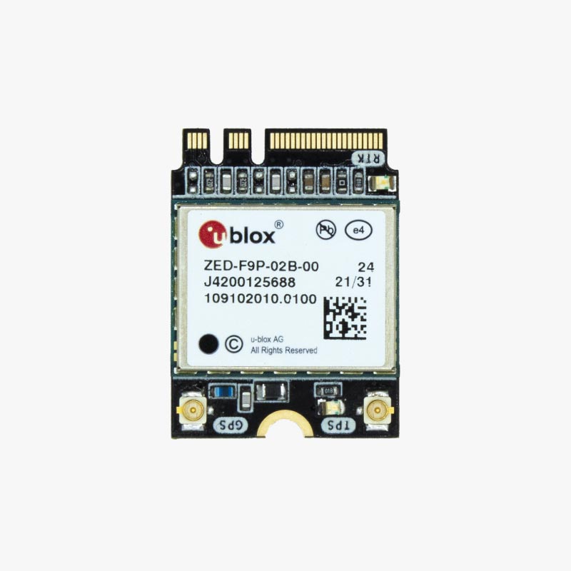
- M2W - M.2 in a form compatible with sockets designed for M.2 wifi cards
- CMS - Raspberry Pi Compute Module 4/5 sandwich board; designed to be sandwiched between the compute module and the carrier board
- RCB - telecom industry standard format for timing boards for cellular base stations
- SR1 - small board with 1 mounting hole, Dupont pins, U.FL and SMA antenna connectors
M2W board type
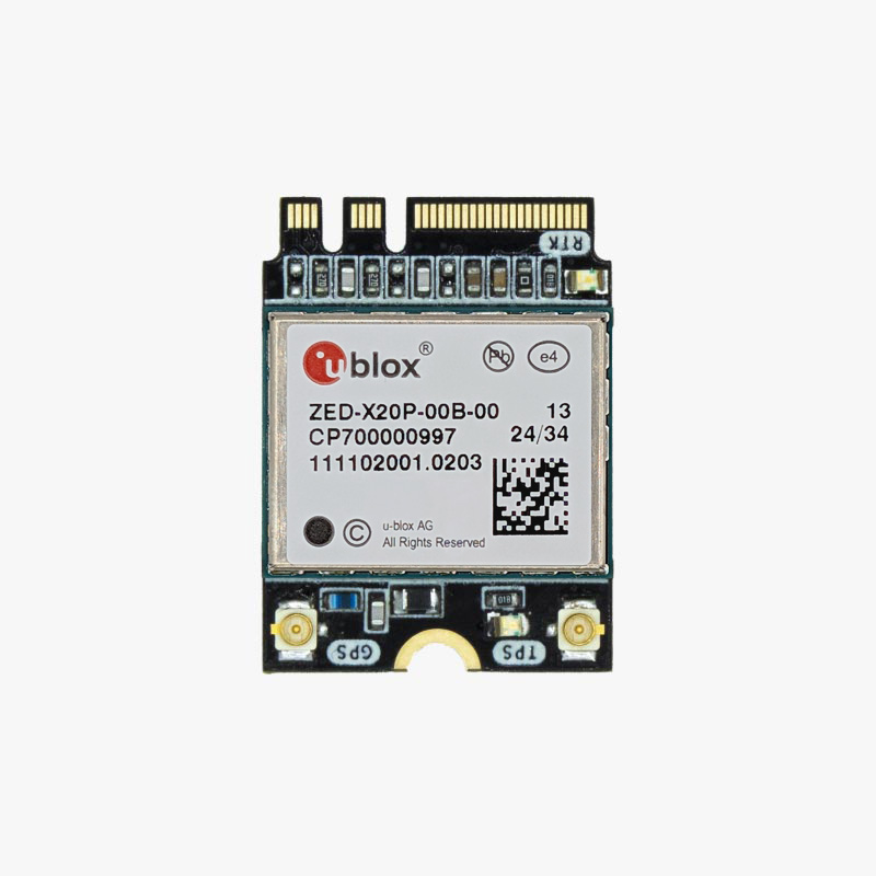
Pin connector: M.2, Key A and Key E (USB and power pins only)
Dimensions: 22mm x 30mm
PPS output: U.FL
Antenna connector: U.FL
ArduSimple make cards in a M.2 form factor, compatible with M.2 slots intended for Wifi cards, with a coouple of different modules:
CMS board type
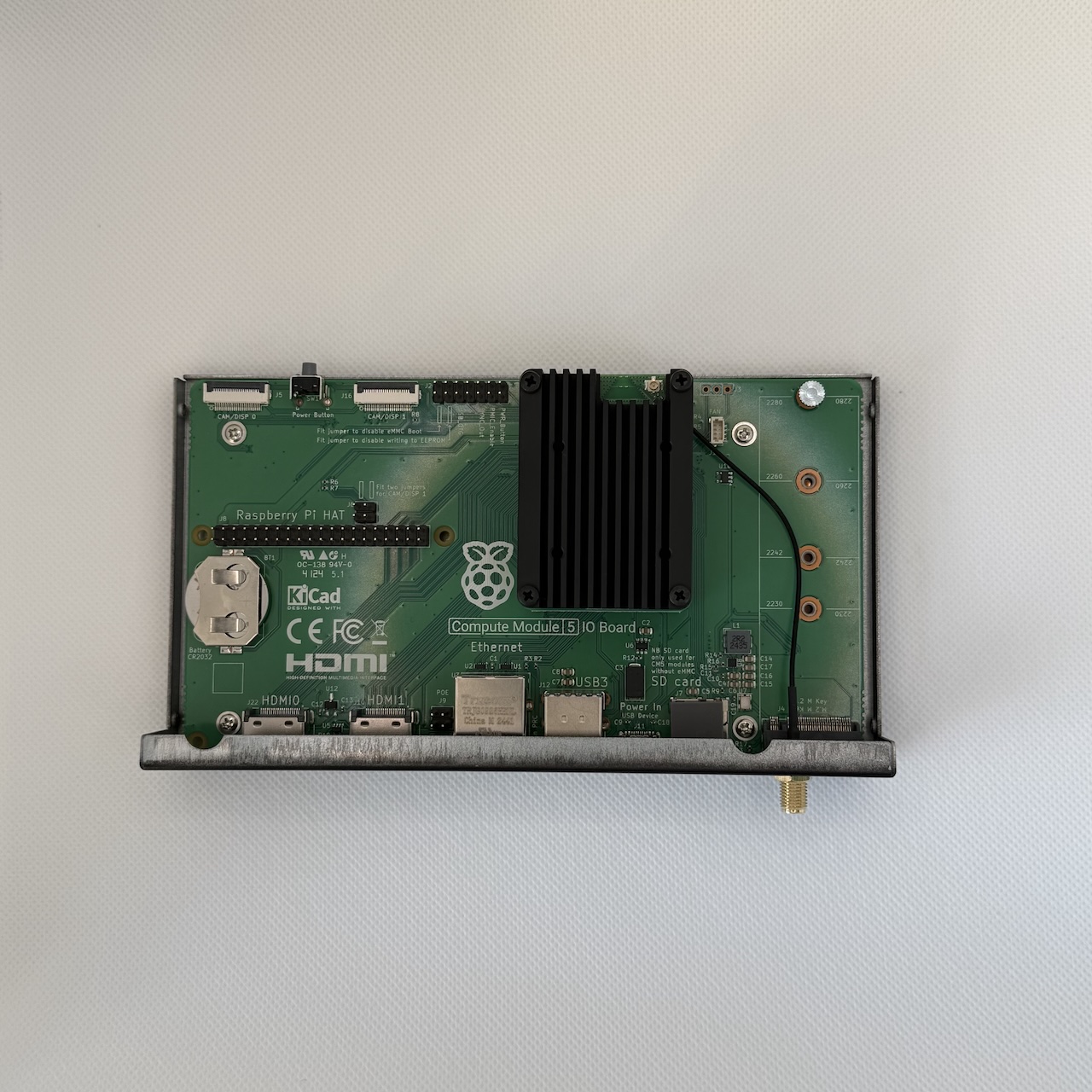
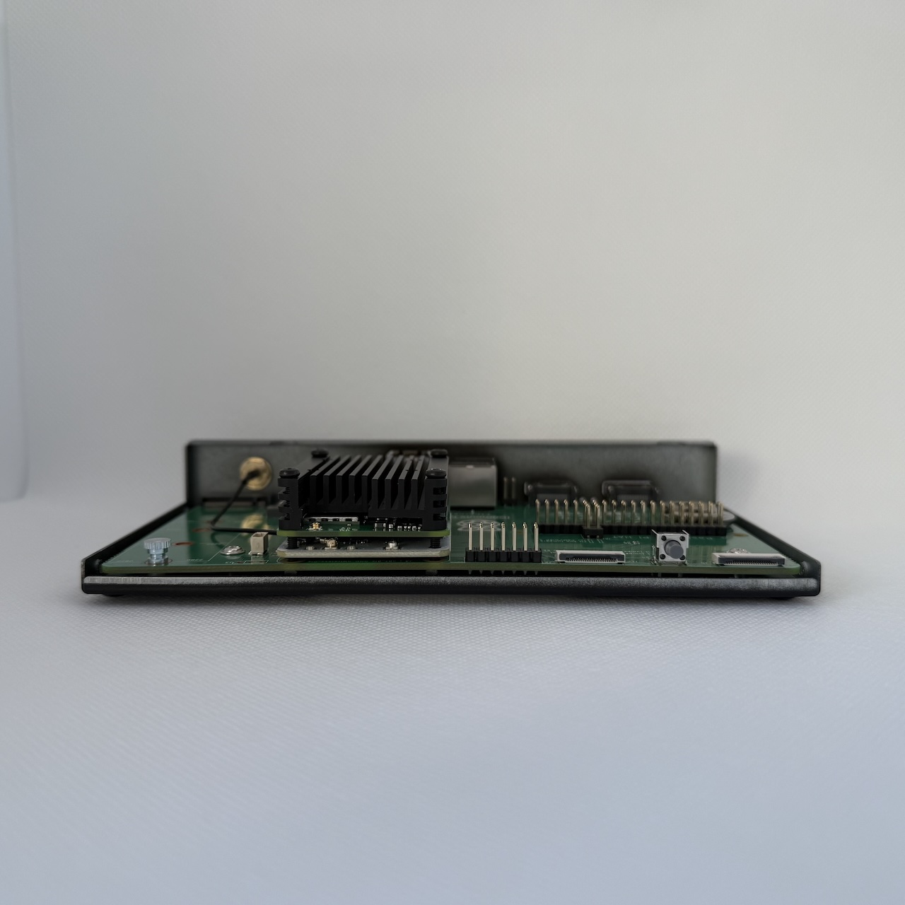
Pin connector: 2 x CM4/CM5 compatible 100-pin, on both sides
Antenna connector: U.FL
Dimensions: 55mm x 40mm (same as CM4/CM5)
Battery: no
They make versions using three different modules, in increasing order of price:
- Essential using u-blox MAX-F10S
- Precision timing lite using u-blox NEO-F10T
- Precision timing using u-blox ZED-F9T
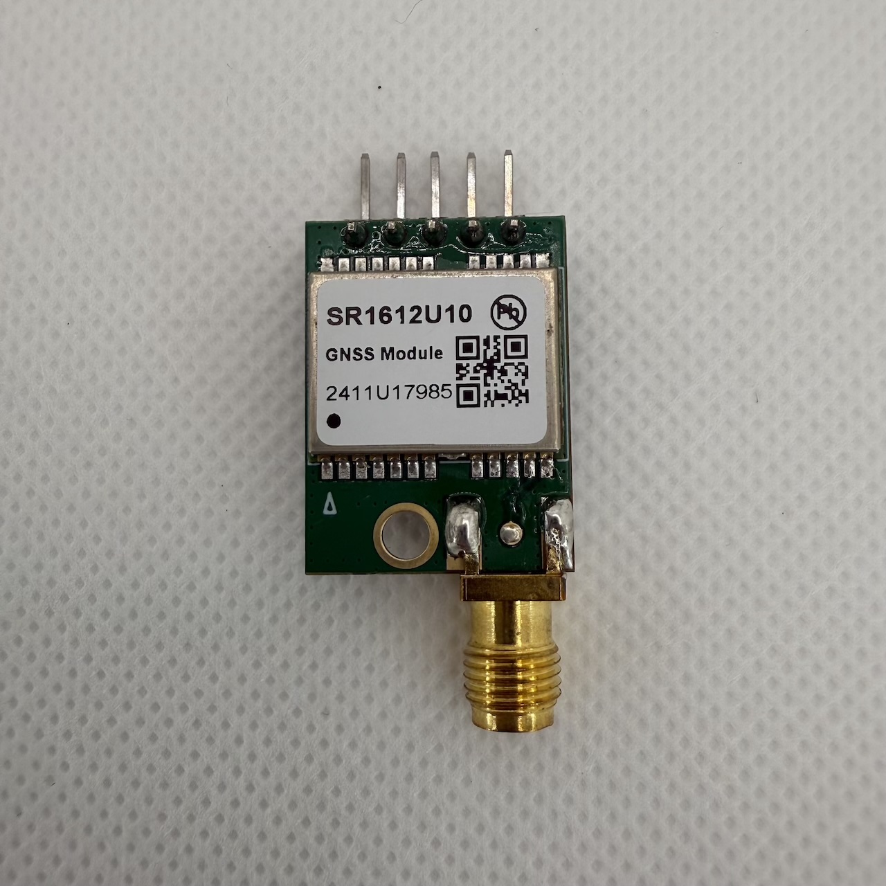
SR1 board types
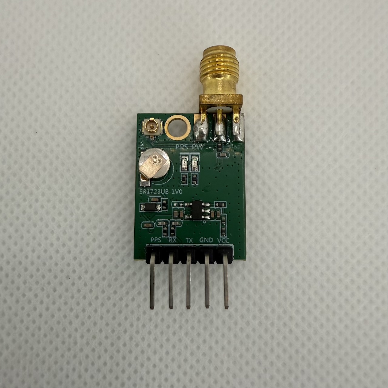
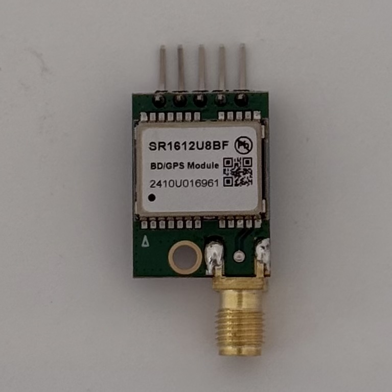
Mounting holes: 1 x M3
Pin connector: 5 x Dupont 2.54mm pins, horizontal
USB: no
Antenna connectors: U.FL and SMA
Dimensions: 17mm x 23mm (excluding connectors); 17mm x 40mm (including connectors)
Battery: yes
Star River make the SR1723 range of boards, which are very inexpensive and an ideal form factor for use with the Compute Module 4/5. Most models are available in their AliExpress store; all of them are available in the Taobao store.
The particular model I would recommend is the SR1723U10 which uses a module with the u-blox M10050-KB chip. On AliExpress, it’s about $7. Note that SR1723U10 is the board name; the module is the SR1612U10.
They also have U7, U8 and U9 models using 7th, 8th and 9th generation u-blox chips. The U7 model is $2 cheaper, but I would recommend spending the extra $2. They also have models using the Zhongke Micro chip and the MTK3333, which I wouldn’t recommend.
RCB board type
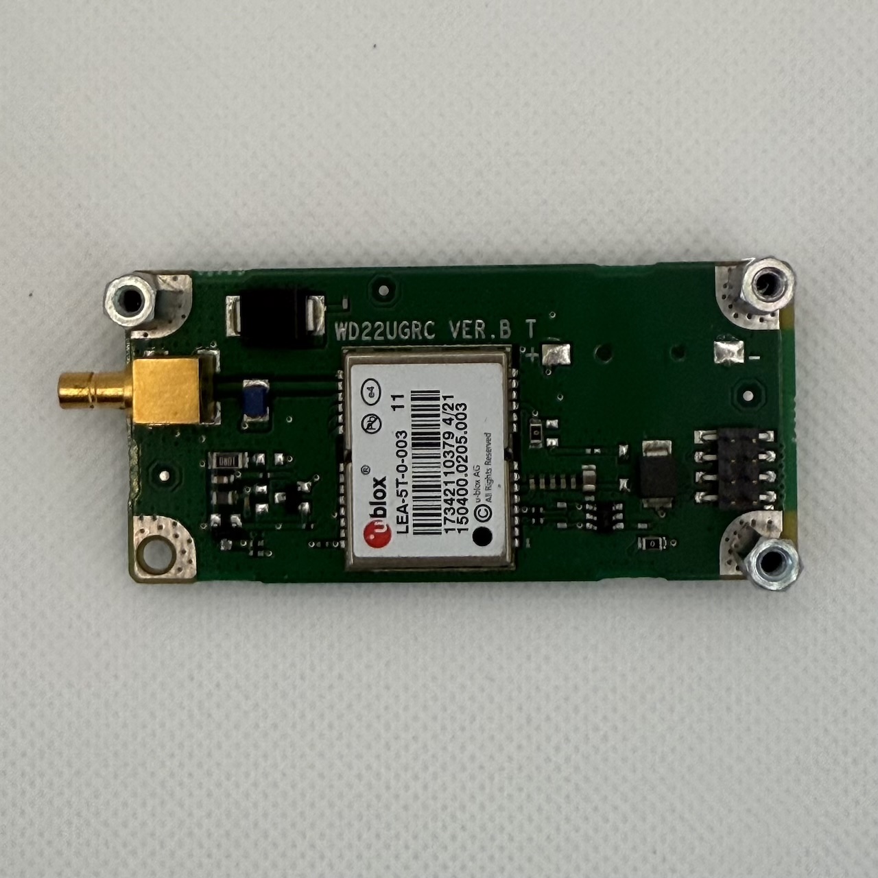
Dimensions: 67mm x 32mm
Mounting holes: 4 x M3
Mounting hole pitch: 60.5mm x 26mm
Pin connector: 2.00mm Dupont 8-pin (4x2)
Antenna connector: SMB male jack
USB: no
Battery: no
I recommend two boards with this type:
- u-blox RCB-F9T; this is available from DigiKey or Mouser; current version ias of September 2025 is the L1/L5 RCB-F9T-1, but there should be a L1/L2/L5 RCB-F9T-2 soon
- Huawei boards using LEA-M8T on eBay; I have bought several from xihu88 store
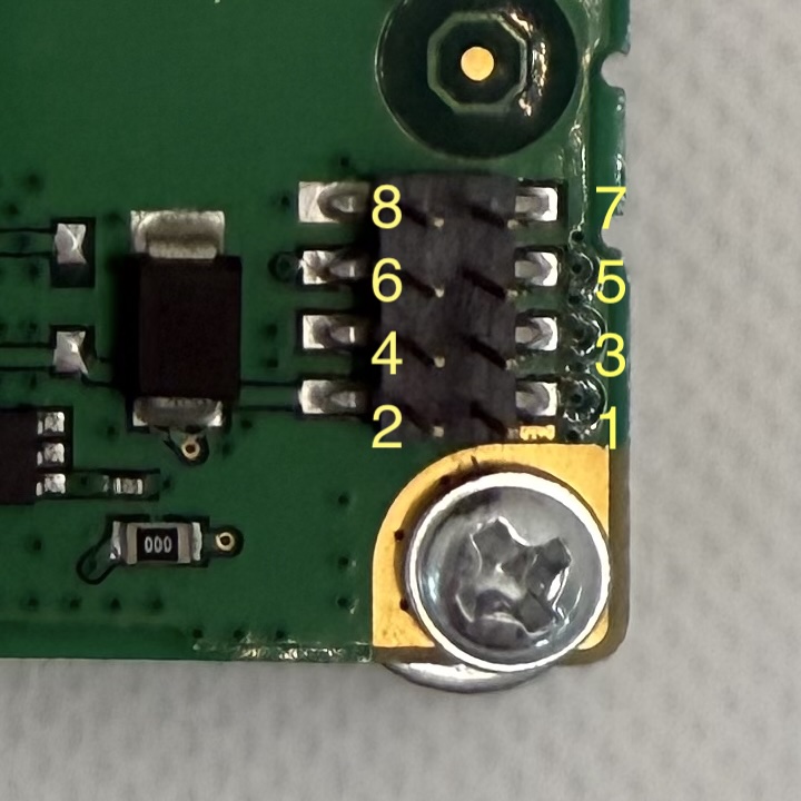
A board in this form factor needs two cables to connect it:
- a cable that plugs into the antenna connector on the board and attaches to the antenna hold in the case: this needs a SMB female (plug) to SMA female bulkhead pigtail; ideal length is about 15cm
- a cable to connect from the pins on the board to the pins on the IO board: you can buy a 20cm cable consisting of a strip of 40 wires, with one end having 2.54mm Dupont 1-pin female connectors and the other end having 2.0mm 2-pin female Dupont connectors AliExpress, AdaFruit, eBay
The pins need to be connected as follows:
| RCB pin no | u-blox pin name | IO header | header pin no | header pin name | description |
|---|---|---|---|---|---|
| 1 | VCC_ANT | HAT | 2 | 5V | Antenna power |
| 2 | VCC | HAT | 1 | 3V3 | Operating power for GPS |
| 3 | TXD | HAT | 10 | UART0_RXD | GNSS to CM4/5 |
| 4 | RST | HAT | Reset - not connected | ||
| 5 | RXD | HAT | 8 | UART0_TXD | CM4/5 to GNSS |
| 6 | TP1 | J2 | 9 | SYNC_OUT | Time pulse |
| 7 | TP2 | HAT | 12 | GPIO18 | Time pulse 2 - only on RCB-F9T |
| 8 | GND | HAT | 6 or 14 | GND | Ground |
If you orient the board so that SMB connector is on the left, then pin 1 is the pin at the bottom right.
Pin 1 supplies power to the antenna; the precise range of allowed voltages depends on the board. All boards appear to accept a range of 3.3-5V.