Building a system using a BeagleY-AI
Building the computer
Only three parts are required:
- the BeagleY-AI itself
- a microSD card (32GB is plenty)
- a 5V 3A USB-C power supply
Case
The BeagleY-AI is mechanically compatible with the Raspberry Pi 5, so cases designed for the Raspberry Pi 5 work with the BeagleY-AI.
The Raspberry Pi Bumper case works nicely as a minimalist case.
For something fully enclosed, I suggest the Waveshare Industrial Grade Metal Case (D) for Raspberry Pi 5. The following features make this work well for this application:
- space for NVMe drive and cooler
- made of steel, so a GPS board can be attached using magnets
- sufficient space inside the case to attach a GPS board to the underside of the case top
- has SMA cutouts, which can be used to connect a GPS antenna via an SMA female bulkhead pigtail
NVMe drive
The Geekworm X1001 looks most suitable since it leaves the 40-pin header exposed. (I haven’t tried this yet.)
Cooling
The Raspberry Pi Active Cooler is supposed to work. (I haven’t tried this yet.)
Connecting an external receiver
I haven’t tried it, but this would work straightforwardly with a bumper case. An external receiver with a PPS output that uses an SMA female connector could be connected using an SMA male to Dupont female test cable to header pin 33 and a ground pin. The serial connection would use a USB port.
Using an internal board
The most important point is that a Raspberry Pi GPS HAT will not work if you want to make use of PHC hardware timestamping. The hardware timestamped PPS input can be made available only on header pin 33, but Raspberry Pi GPS HATs wire PPS output to header pin 12 (if they wire it anywhere).
This means there is a mechanical challenge of how to mount the GPS board on the case.
With the Waveshare case, I recommend:
- select a small GPS board that has 4 mounting holes that accept M3 screws and a U.FL antenna connector
- attach 4 magnetic stands with M3 female sockets to the mounting holes on the board using M3 screws
- attach the magnets to the underside of the case top
- use a U.FL to SMA female bulkhead pigtail to provide an SMA connector on the case connected to the U.FL antenna connector on the board
With the bumper case, I recommend:
- select a small GPS board that has a single mounting hole that accepts an M2.5 screw and that has an SMA antenna connector
- use a 15 mm M2.5 female-female standoff (preferably nylon)
- use an M2.5 screw through the base of the bumper case to secure the standoff to the case and board; use the hole in the corner next to the USB-C connector
- use an M2.5 nylon screw to secure the GPS board to the standoff
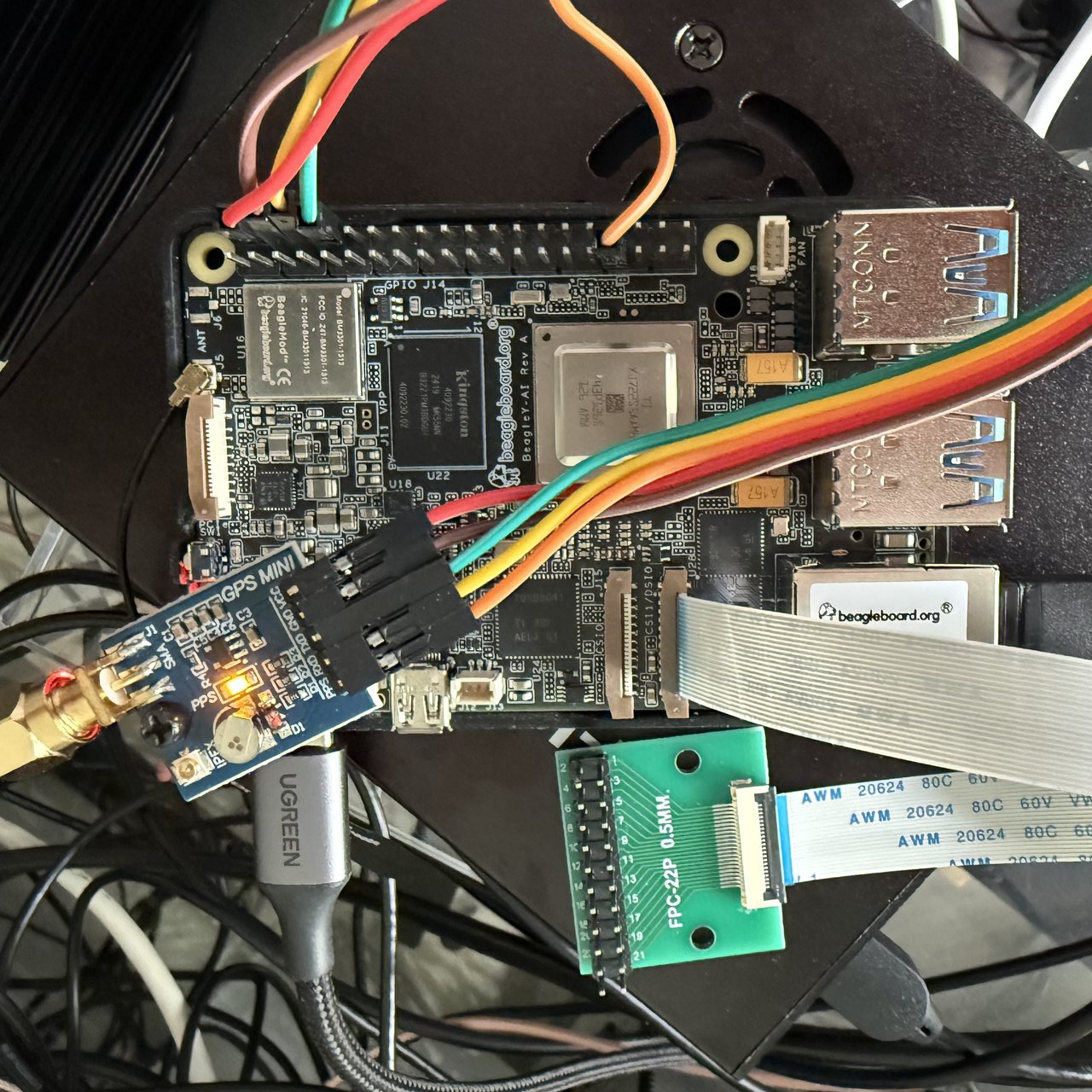
Wire the GPS as follows:
| GPS pin | Wire colour | HAT pin | HAT function |
|---|---|---|---|
| VCC | red | 4 | 5V |
| GND | brown | 6 | Ground |
| RXD | yellow | 8 | GPIO 14 (UART TX) |
| TXD | green | 10 | GPIO 15 (UART RX) |
| PPS | orange | 33 | GPIO 13 (PWM1) |
This is assuming you will use the recommended overlays.