Measuring systematic PPS bias on the Raspberry Pi 5
Many enthusiasts build stratum 1 NTP servers using Raspberry Pis. It’s a great platform to do it on. I built my first time server on a Raspberry Pi 3B back in 2018. When you have completed the build, you can look at the offsets reported by the NTP server, which are typically in the microsecond range, and congratulate yourself, as I did, on having microsecond accurate time. Unfortunately in almost all cases that is an illusion. What those offsets tell you is precision: how stable your clock is. The NTP server has absolutely no way to know how closely the PPS pulses it is being fed correspond to UTC time. What it does is assume that the PPS pulses have no systematic bias, and on that assumption tracks the difference between its estimate of UTC time and the system clock. But in fact, when you use kernel PPS timestamping your pulses are guaranteed to have a small bias: the kernel timestamp always records a time after the edge has happened, and there’s lots that happens between the pulse edge entering the machine and the kernel taking its timestamp.
TLDR; this bias is ~11–12 µs on average. Disabling the L1 low power state on the RP1 chip reduces it by ~5 µs.
However, it’s not obvious how you measure this. In this post, I want to explain two techniques: one uses PPS echo, an external time interval counter and eBPF; the other uses GPIO polling. I used AI agents (Claude Code Fable 5.1 and Codex GPT-6 Astra) to help me do this, but I wrote this post myself.
PPS echo with a tinyGTC
The kernel PPS subsystem has an echo feature. The idea is that the kernel can immediately after timestamping a pulse edge then generate a pulse on another pin. The purpose is to allow you to calibrate timestamping delay.
Recently Josh Blake developed a new overlay for the Raspberry Pi 5 that implements the echo feature.
This is included in the latest Raspberry Pi Kernel, starting with version 1:6.12.70-1+rpt1 (February 2026).
If you have the file /boot/firmware/overlays/pps-rp1.dtbo, then you have it available.
To use the overlay, comment out any existing dtoverlay=pps-gpio,gpiopin=18 line and add
dtoverlay=pps-rp1,pin=18,echo
To make use of the echo feature, you need a time interval counter, which is a device that can very accurately measure the time between two pulses. The tinyGTC works well for this. I already blogged about using it with PTP hardware clocks.
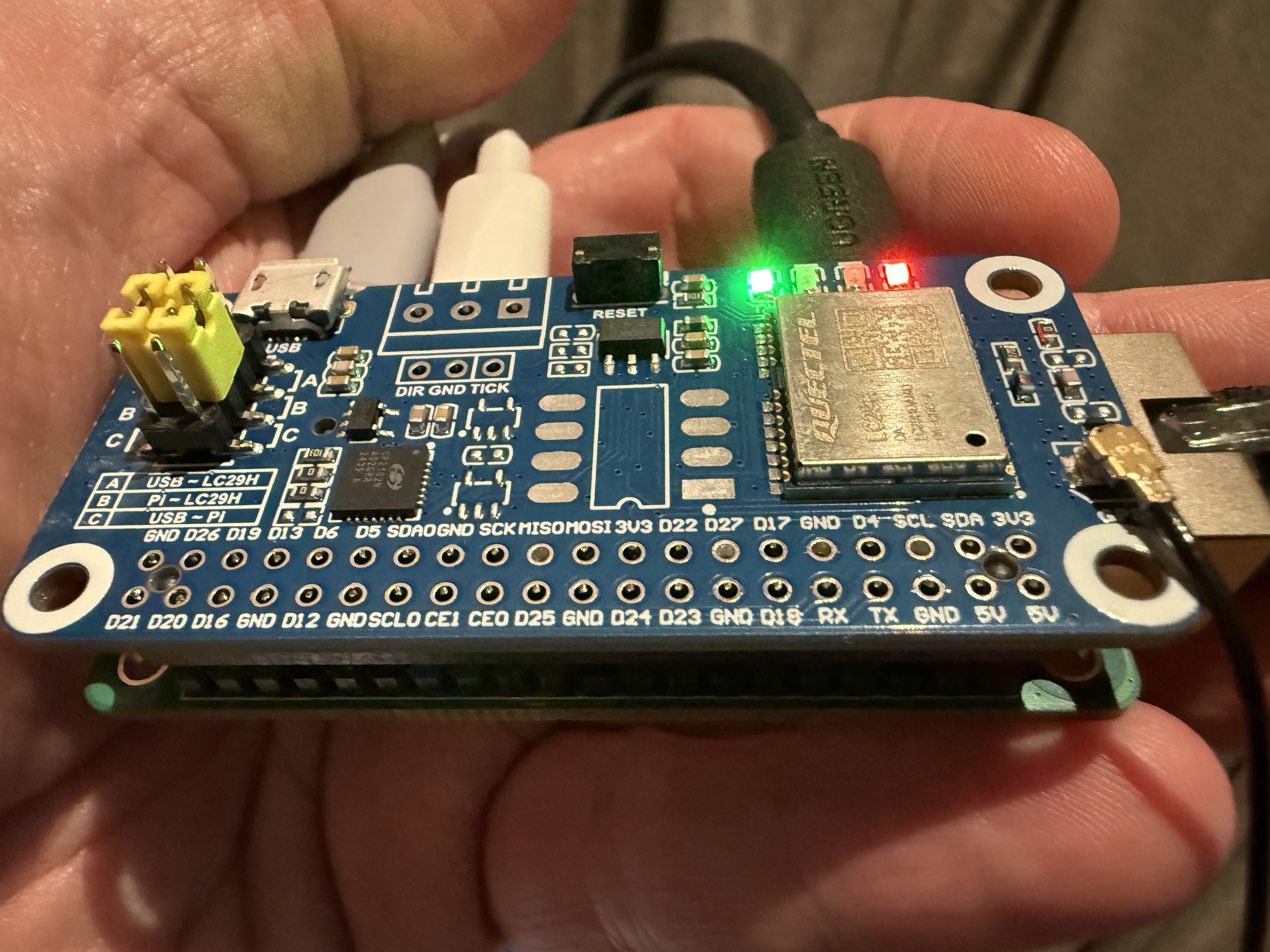
To make the measurements, you connect the OUT connector of the tinyGTC to the PPS input of the Pi, and you connect the echoed PPS output from the PI to input A on the tinyGTC. The tinyGTC input and output ports use SMA female connectors and the Raspberry Pi uses Dupont male pins. So you need two cables with SMA male on one end and Dupont female on the other. You can buy suitable cables on eBay or AliExpress (they are called SMA test cables) or, if you are handier than me, you can probably make them yourself. The cables typically have a red and a black Dupont connector. The red connector of the OUT cable should be plugged into physical pin 12. The red connector of the IN cable should be plugged into physical pin 11. The black connectors need to be plugged into GND pins: pin 6 and pin 9 are convenient for this.
You then configure OUT to have an aligned PPS at 1Hz and then measure the NCO against input A. You also need to run a program to enable PPS_ECHOASSERT through the kernel PPS API in order to get an echo. Leaving it overnight I get something like this.
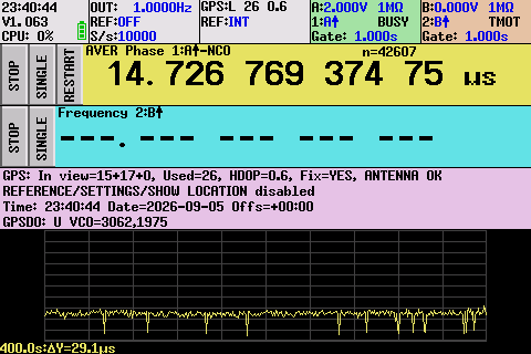
This is showing a delay of ~14.7 µs over approximately 43,000 measurements.
Initially I controlled the tinyGTC through its touchscreen. One nice feature of the tinyGTC is that it has an SCPI interface for programmatic control. It turned out that the agent was able to figure out from the tinyGTC website how to drive it using Python through this interface, with very little input from me; I only had to explain how aligned PPS worked. This allows an agent to do all sorts of interesting experimentation autonomously.
But this does not mean that bias is 14.7 µs, because there is significant elapsed time between the kernel taking the timestamp and the pulse edge being emitted on the output pin.
It is convenient to give names to instants of time:
- IN - the time the physical edge enters the PPS input pin
- STAMP - the time the kernel records the timestamp
- WRITE - the time that the kernel issues the GPIO output instruction for the echo edge
- OUT - the time the physical edge exits the PPS output pin
We are interested in STAMP - IN. But we are measuring OUT - IN. We therefore need to estimate OUT - STAMP.
The time between STAMP and WRITE can be estimated by inserting probes into the kernel using bpftrace, which builds on Linux’s eBPF feature. This requires a bit of care because the probes themselves have overhead, but this can be compensated for. Using bpftrace produces an estimate of ~2 µs for WRITE - STAMP.
The remaining interval we need to estimate is OUT - WRITE, and I do not know any way to measure it. But based on the RP1 datasheet, I estimate it at no more than 1 µs.
So doing the math:
STAMP - IN = (OUT - IN) - (WRITE - STAMP) - (OUT - WRITE) = 14.7 - 2 - 1 = 11.7 µs
These measurements are done with the machine mostly idle and in its default configuration.
The obvious next questions are where is it spending 11.7 µs and can this be reduced.
It turns out that the biggest single contributor to the 11.7 µs is the RP1 wake latency.
The RP1 has an L1 low power state, and
if the machine is not busy, the RP1 enters this state between each pulse.
You can prevent the RP1 entering L1 state by writing 0 to /sys/bus/pci/devices/0002:01:00.0/link/l1_aspm;
writing 1 enables it.
Disabling the L1 state reduces OUT - IN by ~5.5 µs and it turns out all the delay from L1 is before STAMP.
So this reduces STAMP - IN to ~6.2 µs, and also reduces the jitter.
You can also see this in the chart in the screenshot: the downward spikes are ~5.5 µs,
presumably corresponding to when the RP1 was busy.
I subsequently found that the RP1 datasheet documents a wake latency of approximately 5 µs.
Fixing the CPU frequency to 2.4GHz reduces it further by ~1 µs, bringing STAMP - IN down to ~5.2 µs.
GPIO polling
After doing the above, it occurred to me that there might be a simpler way. Over the last month or so I have implemented a new feature for SatPulse which allows it to read PPS timestamps over a serial line. I wanted this to work on macOS (via a USB-serial converter), but macOS does not have kernel timestamping, nor does the kernel provide a system call to notify an application of a change in the state of a modem control line. This meant I had to implement it by polling: repeatedly reading the modem control status to see when the status changed. There is a fancy adaptive/predictive algorithm to keep CPU-usage minimal. I implemented this on Linux. I also did some measurements on Linux comparing polling and kernel timestamping. I have Linux machines with PTM which allows the system clock to be accurate to tens of nanoseconds, so I can make these measurements very accurately. It turns out that the polling method has worse jitter than kernel timestamping but much less bias. This is a little unexpected at first, but obvious after you think about it: with kernel timestamping the timestamp is always after the pulse; with polling we measure before and after and take the midpoint, so any bias is limited to the time taken for the poll (this is assuming a modem status read actually performs a USB transaction).
So my thought was maybe we can do the same thing with GPIO. The idea is to poll the GPIO and at the same time read kernel timestamps, and then compare them.
There are a couple of problems.
The portable way to read a GPIO state is via libgpiod, which uses an ioctl to access a GPIO character device (e.g. /dev/gpiochip0),
but this cannot be done while the pps-rp1 or pps-gpio overlays are working.
A portable solution is to request edge events from the GPIO character device, which are generated in an interrupt handler
similarly to how the PPS GPIO driver generates timestamps.
This requires unloading the PPS GPIO driver.
On a Raspberry Pi, a superior approach is to read the GPIO input register through /dev/gpiomem0 (/dev/gpiomem on earlier Pis),
which can work at the same time as the PPS GPIO driver.
The other problem is that reading the GPIO causes the RP1 to be busy, which, as we saw, makes a big difference to the measurement. Claude Fable suggested a clever way to solve this. The idea is to poll every other pulse. Let’s suppose we have kernel timestamps K0, K1, K2 and polled timestamps P0, P2. For K0 and K2, the RP1 will be busy, but for K1 it will be idle. We can infer a P1 as the midpoint between P0 and P2. We can then estimate the bias as K1 - P1.
With RP1 L1 enabled, this gives us a bias estimate of 12 µs against 11.7 µs for the echo/tinyGTC method, and with RP1 L1 disabled 7.3 µs against 6.2 µs for the echo/tinyGTC method. This suggests allowing 1 µs for the OUT - WRITE interval is a bit too much. On the other hand PCIe reads take about 1 µs, which implies an unquantified bias in the poll method of up to 1 µs.
Compensating for the bias
If you know the bias, you can compensate for it.
In chrony, if the time pulse is 11 µs late, you would add an offset 11e-6 option to the refclock line.
Update 2026-09-09
I released ppsbias, a program implementing the GPIO polling idea.